2
Installation
Valve and actuator are supplied already as-
sembled by the manufacturer.
For more details on the actuator used,
please refer to the appropriate mounting
and operating instructions.
2.1
Mounting position
The valve can be mounted in any position.
However, the limitations due to the actuator
used must be strictly observed.
CAUTION!
The valve must be installed free of stress and
free of excessive vibrations. If necessary,
support the pipelines near the connections.
Do not install supports on the valve or on the
actuator. Thoroughly flush the pipeline prior
to installation of the valve.
Pipeline routing
To allow the control valve to work properly,
the pipeline upstream and downstream of
the valve must be straight and free of ob-
structions for a length of at least 6 times the
pipe diameter (DN). Contact SAMSON if
this length cannot be met during installation.
Clean out the pipeline thoroughly prior to in-
stalling the valve.
2.2
Arrangement of control valve
Depending on the task to be performed, the
control valve is arranged as illustrated in
Fig. 3.
How the plugs are arranged for mixing or
diverting valves is specified on the label at-
tached to the valve body.
Fail-safe action: Valve shuts off the heating
medium supply or opens the supply of cool-
ing medium.
2.3
Strainer and bypass
We recommend installing a SAMSON
Type 2 N Strainer upstream of the valve,
and upstream of both ports for mixing
valves.
In addition to a bypass line, shut-off valves
should be installed both upstream of the
strainer and downstream of the control valve
so that the plant need not be shut down for
maintenance routines.
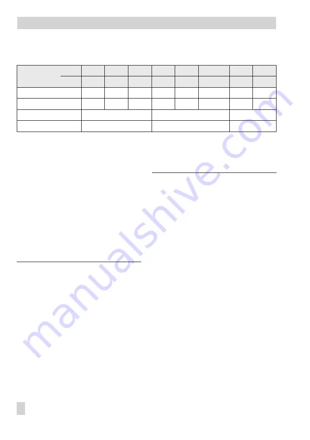
Installation
6
EB 8135/8136 EN
K
VS
and C
V
coefficients, seat diameters and travel
Nominal size
DN
15
20
25
32
40
50
65
80
NPS
½
¾
1
–
1½
2
2½
3
K
vs
coefficients
4
6.3
8
16
20
32
50
80
C
v
coefficients
5
7.5
9.4
–
23
37
60
94
Seat diameter
mm/in
24 mm · 0.94”
40 mm · 1.57”
65 mm · 2.56”
Travel
mm/in
15 mm · 0.59”
15 mm · 0.59”
15 mm · 0.59”


