background image

Function

WE

Configuration

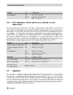
Underfloor heating

OFF
25.0 °C

5.0 °C/day

45.0 °C

4 days

0.0 °C/day

0

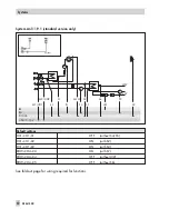
HC1–CO1–05 = ON
Start temperature for drying of jointless floors /
20.0 to 60.0 °C
Temperature increase for drying of jointless floors /
1.0 to 10.0 °C/day
Max. temperature for drying of jointless floors /
2.0 to 60.0 °C
Max. temperature sustaining time for drying of jointless
floors / 1 to 10 days
Temperature reduction for drying of jointless floors /
0.0 to 10.0 °C/day
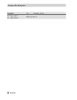
Start drying of jointless floors / 0 to 5 (meaning of 0 to 3
on page 59, 4 = drying process successfully completed,
5 = too large system deviation during drying process
occurred

6.4

Deactivation based on the outdoor temperature

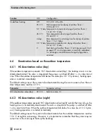
6.4.1 HC deactivation value (day)

If the outdoor temperature exceeds 'HC1 deactivation value (day)', the heating circuit is imme-
diately deactivated. The valve is closed and the pump is switched off after t = 2 x valve transit
time. When the outdoor temperature falls below this value (less 0.5 °C hysteresis), heating oper-
ation is restarted immediately.
The default setting causes the system to be deactivated during the warm season when the out-
door temperature reaches 22.0 °C.

Parameter

WE

Parameter settings

HC1 deactivation value (day)

22.0 °C

Refer to section 3.1

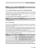
6.4.2 HC deactivation value (night)

If the outdoor temperature exceeds 'HC1 deactivation value (night)' outside the times-of-use, the
heating circuit is immediately deactivated. The valve is closed and the pump is switched off after
t = 2 x valve transit time. When the outdoor temperature falls below this value (less 0.5 °C hyster-
esis), heating operation is restarted immediately.
The default setting causes the system to be deactivated when the outdoor temperature reaches
15.0 °C at night to save energy. However, it is important tor remember that the system requires
some time in the morning to heat up the building.

60

EB 5610 EN

Functions of the heating circuit

Содержание trovis 5600

Страница 1: ...TROVIS 5600 Automation System TROVIS 5610 Heating and District Heating Controller Mounting and Operating Instructions EB 5610 EN Electronics from SAMSON Firmware version 1 40 Edition December 2014...

Страница 2: ...nting and Operating Instructions EB 5610 EN 2 EB 5610 EN Controller versions DANGER indicates a hazardous situation which if not avoided will result in death or serious injury WARNING indicates a haza...

Страница 3: ...e language setting 28 3 7 Configuring the controller and changing parameter settings 29 3 7 1 Changing the system code number 30 3 7 2 Activating or deactivating functions 30 3 8 Setting parameters 32...

Страница 4: ...Circulation pump operation during storage tank charging 76 7 7 Priority operation 76 7 7 1 Reverse control 76 7 7 2 Set back operation 77 7 8 Forced charging of the DHW storage tank 78 7 9 Thermal dis...

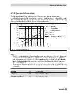
Страница 5: ...Collective fault alarm 91 10 Installation 92 11 Electrical connection 94 12 Interfaces 98 12 1 Memory pen 99 12 2 TROVIS VIEW 99 13 Appendix 100 13 1 Configuration levels 100 13 2 Parameter levels 111...

Страница 6: ...m deviations occur see p 59 1 20 old 1 30 new Internal revisions 1 30 old 1 40 new Changed setting ranges for the following parameters refer to section 13 2 Outdoor temperature four point characterist...

Страница 7: ...elow in the order described 1 Install the controller and connect the wiring Refer to sections 10 and 11 NOTICE The wiring differs depending on the system Refer to sections 5 and 11 After the controlle...

Страница 8: ...l substances which were necessary for them to function For this rea son do not dispose this kind of equipment together with your other household waste Instead dispose of your waste equipment by handin...

Страница 9: ...4 Operation menu for setting the operating mode and special times of use 4 Manual menu for setting the controller outputs 4 Times of use menu for setting the time schedules 4 Setup menu for entering t...

Страница 10: ...key only appears when manual mode is active Press this key to go to the Manual menu Press this key to go to the Times of use menu The current day of the week MON TUE WED THU FRI SAT SUN is displayed...

Страница 11: ...rmation menu contains current details on the control process and the controller If the controller detects an error an error list is displayed on the first screen of the Information menu Refer to secti...

Страница 12: ...ing systems with two control circuits Select screen displaying information on the DHW sensors for DHW heating if required Read set points Select screen displaying an overview Overview of control circu...

Страница 13: ...the schematics of the currently se lected system Select screen displaying information on the device controller Information on the device controller The currently selected system code number the contro...

Страница 14: ...erature exceeds the HC day or night deactivation value Section 3 1 Day Regardless of the programmed times of use and summer mode the days set points are used by the controller Section 3 1 The heating...

Страница 15: ...d for long periods e g dur ing vacations A maximum of ten time periods can be defined in which the controller switches to day night or stand by mode regardless of the programmed operating mode After a...

Страница 16: ...current time hour while the start and stop dates are set to the current date Press the start time button 2 Set the start time in steps of 15 minutes Press the stop time button 3 Set the stop time in...

Страница 17: ...nd heating systems with two control circuits If required copy the special times of use settings for the heating circuit to the DHW circuit If required copy the special times of use settings for the DH...

Страница 18: ...atic mode the day set points are used during the times of use and the night set points outside the times of use 2 3 1 Changing the times of use The following instructions describe the procedure starti...

Страница 19: ...vidually for each day of the week Note The settings for individual days MON TUE etc have priority over the settings for multiple days The set tings for weekdays MON FRI and weekend SAT SUN have priori...

Страница 20: ...Deleting times of use Press the start or stop time button of the time of use you want to delete Delete the time of use Return to Time of use menu or Return to start screen Manual mode EB 5610 EN 20...

Страница 21: ...be adapted to your requirements 4 Change set points and deactivation values refer to section 3 1 4 Activate or deactivate functions refer to section 3 7 2 4 Set parameters refer to section 3 8 Further...

Страница 22: ...22 EB 5610 EN Setup settings B C D A A...

Страница 23: ...y changing an absolute value DHW set points The DHW temperature during the times of use day and outside the times of use night can be defined by changing DHW set points The set points are defined by c...

Страница 24: ...nt is acti vated dark background Standard version and heating systems with two control circuits If required select the set points for DHW heat ing If required select the button for night set point Cha...

Страница 25: ...procedure starting from the start screen see page 9 Open the Setup menu Select menu item for contrast and brightness The current contrast setting is activated dark background Adjust contrast Press bu...

Страница 26: ...m the start screen see page 9 Open the Setup menu Select menu item for date and time The date setting button is activated dark background Change the date Press button for the time setting Change the t...

Страница 27: ...wing instructions describe the procedure starting from the start screen see page 9 Open the Setup menu Select menu item for calibrate clean display Press Calibrate display button A cross appears at di...

Страница 28: ...activated for 30 seconds During the countdown the display can be cleaned with a damp microfiber cloth Return to start screen 3 6 Changing the language setting The following instructions describe the p...

Страница 29: ...l functions and parameter levels Sections 13 1 and 13 2 4 Screen displaying the system schematics 4 Configuration level CO level HC1 CO1 only for systems with HC1 DHW CO4 only for systems with DHW HC1...

Страница 30: ...level see page 29 Open the screen displaying the system schematics The schematics of the currently valid system are shown see section 5 Select a different system Confirm the new system System saved ap...

Страница 31: ...er the other Activate or deactivate the function block Function blocks with function block parameters Press function block parameter button Select a function block parameter Set the function block par...

Страница 32: ...pear Select the parameter level The parameters of the activated parameter level are listed on the screen Go directly to the parameter or Select parameters one after the other Set the parameter Go to t...

Страница 33: ...n manual mode The following instructions describe the procedure starting from the start screen see page 9 Open the Manual menu The outputs of the control circuit specified in the sec ond row are shown...

Страница 34: ...t screen The hand icon under the date indicates active manual operation The key is replaced by the key on the start screen Exit manual mode Exit manual mode The key is replaced by the key on the start...

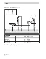
Страница 35: ...ngs HC1 CO1 01 OFF without S4 S5 HC1 CO1 02 ON with S2 HC1 CO1 03 ON with S3 See fold out page for wiring required for functions EB 5610 EN 35 Systems BE BA Pt 1000 3 Pkt 0 10 V S3 S1 M1 UO1 S2 P1 S4...

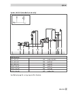
Страница 36: ...CO1 01 OFF without S4 S5 HC1 CO1 02 ON with S2 HC1 CO1 03 OFF without S3 See fold out page for wiring required for functions 36 EB 5610 EN Systems BE BA Pt 1000 3 Pkt 0 10 V S2 S4 S5 S3 S1 P1 M1 UO1...

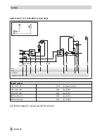
Страница 37: ...settings HC1 CO1 01 OFF without S4 S5 HC1 CO1 02 ON with S2 HC1 CO1 03 ON with S3 DHW CO4 01 ON with S7 See fold out page for wiring required for functions EB 5610 EN 37 Systems BE BA Pt 1000 3 Pkt 0...

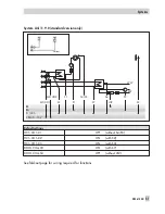
Страница 38: ...ettings HC1 CO1 01 OFF without S4 S5 HC1 CO1 02 ON with S2 HC1 CO1 03 OFF without S3 DHW CO4 01 ON with S7 See fold out page for wiring required for functions 38 EB 5610 EN Systems BE BA Pt 1000 3 Pkt...

Страница 39: ...ut S4 S5 HC1 CO1 02 ON with S2 HC1 CO1 03 OFF without S3 DHW CO4 01 ON with S7 DHW CO4 02 ON with S8 DHW CO4 05 OFF without S6 See fold out page for wiring required for functions EB 5610 EN 39 Systems...

Страница 40: ...ersion only Default settings DHW CO4 01 ON with S7 DHW CO4 02 ON with S8 DHW CO4 03 ON with S3 See fold out page for wiring required for functions 40 EB 5610 EN Systems BE BA Pt 1000 3 Pkt 0 10 V WW K...

Страница 41: ...ult settings DHW CO4 01 ON with S7 DHW CO4 02 ON with S8 DHW CO4 03 ON with S3 DHW CO4 05 OFF without S6 See fold out page for wiring required for functions EB 5610 EN 41 Systems BE BA Pt 1000 3 Pkt 0...

Страница 42: ...t settings DHW CO4 01 ON with S7 DHW CO4 02 ON with S8 DHW CO4 03 OFF without S3 DHW CO4 05 OFF without S6 See fold out page for wiring required for functions 42 EB 5610 EN Systems BE BA Pt 1000 3 Pkt...

Страница 43: ...ings DHW CO4 03 ON with S3 DHW CO4 04 OFF without UI2 See fold out page for wiring required for functions EB 5610 EN 43 Systems BE BA Pt 1000 3 Pkt 0 10 V S3 S1 M1 UO1 P1 UI2 WW F KW Compact version W...

Страница 44: ...nl 1 9 1 Default settings DHW CO4 03 ON with S3 See fold out page for wiring required for functions 44 EB 5610 EN Systems BE BA Pt 1000 3 Pkt 0 10 V WW KW P1 S1 M1 UO1 S3 Compact version Without UO1 0...

Страница 45: ...CO1 01 OFF without S4 S5 HC1 CO1 02 ON with S2 HC1 CO1 03 ON with S3 DHW CO4 01 ON with S7 DHW CO4 02 OFF without S8 See fold out page for wiring required for functions EB 5610 EN 45 Systems BE BA Pt...

Страница 46: ...CO1 01 OFF without S4 S5 HC1 CO1 02 ON with S2 HC1 CO1 03 ON with S3 DHW CO4 01 ON with S7 DHW CO4 02 OFF without S8 See fold out page for wiring required for functions 46 EB 5610 EN Systems BE BA Pt...

Страница 47: ...01 OFF without S4 S5 HC1 CO1 02 ON with S2 HC1 CO1 03 ON with S3 DHW CO4 01 ON with S7 DHW CO4 02 ON with S8 DHW CO4 05 OFF without S6 See fold out page for wiring required for functions EB 5610 EN 47...

Страница 48: ...m Anl 3 5 0 Default settings HC1 CO1 03 ON with S3 See fold out page for wiring required for functions 48 EB 5610 EN Systems BE BA Pt 1000 3 Pkt 0 10 V S3 S1 M1 UO1 P1 Compact version Without UO1 0 to...

Страница 49: ...CO1 01 OFF without S4 S5 HC1 CO1 02 ON with S2 HC1 CO1 03 ON with S3 DHW CO4 01 ON with S7 DHW CO4 03 ON with S6 See fold out page for wiring required for functions EB 5610 EN 49 Systems BE BA Pt 1000...

Страница 50: ...O1 01 OFF without S4 S5 HC1 CO1 02 ON with S2 HC1 CO1 03 ON with S3 DHW CO4 01 ON with S7 DHW CO4 02 ON with S8 See fold out page for wiring required for functions 50 EB 5610 EN Systems WW BE BA Pt 10...

Страница 51: ...1 OFF without S4 S5 HC1 CO1 02 ON with S2 HC1 CO1 03 ON with S3 DHW CO4 03 ON with S7 DHW CO4 04 OFF without UI2 See fold out page for wiring required for functions EB 5610 EN 51 Systems BE BA Pt 1000...

Страница 52: ...S5 HC1 CO1 02 ON with S2 HC1 CO1 03 ON with S3 DHW CO4 03 ON with S7 DHW CO4 04 OFF without UI2 DHW CO4 05 OFF without S6 See fold out page for wiring required for functions 52 EB 5610 EN Systems BE...

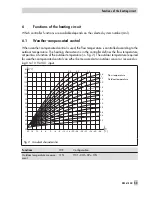
Страница 53: ...nction of the outdoor temperature Fig 2 The outdoor temperature required for weather compensated control can either be measured at an outdoor sensor or received us ing 0 to 10 V at UI1 input Functions...

Страница 54: ...e flow tem perature to increase By varying the parameters Gradient and Level you can adapt the characteristic to your individ ual requirements The gradient needs to be increased if the room temperatur...

Страница 55: ...sign 90 70 Gradient approx 1 8 4 New building radiator design 70 55 Gradient approx 1 4 4 New building radiator design 55 45 Gradient approx 1 0 4 Underfloor heating depending on arrangement Gradient...

Страница 56: ...Parameters WE Parameter settings HC1 day set point Refer to section 3 1 HC1 night set point 56 EB 5610 EN Functions of the heating circuit...

Страница 57: ...nts for day and night must be set Section 3 1 if the supplementary functions such as Optimiza tion or Flash adaptation the room temperature must be measured for both these func tions are configured Th...

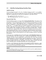
Страница 58: ...0 0 C 6 2 Fixed set point control During the times of use the flow temperature can be controlled according to a fixed set point Outside the times of use the controller regulates to a reduced flow temp...

Страница 59: ...rature reduction downwards When temperature reduction is set to 0 the temperature maintaining phase moves directly to the automatic mode By setting Start drying of jointless floors to 1 the drying of...

Страница 60: ...he pump is switched off after t 2 x valve transit time When the outdoor temperature falls below this value less 0 5 C hysteresis heating oper ation is restarted immediately The default setting causes...

Страница 61: ...liest start date for summer mode to Latest stop date for summer mode If the mean daytime temperature exceeds the limit entered in Outdoor temperature for summer mode on the number of successive days d...

Страница 62: ...0 C h Delay increasing outdoor tem perature OFF 3 0 C h HC1 CO5 06 ON Outdoor temperature delay 1 0 to 6 0 C h Note The Outdoor temperature delay setting applies to both function blocks HC1 CO5 05 an...

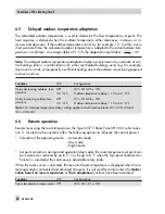
Страница 63: ...door temperature OFF 120 min HC1 CO1 06 ON Preheating time 0 to 360 min Parameter WE Parameter settings HC1 day set point Refer to section 3 1 6 7 2 Optimization based on room temperature This functio...

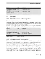
Страница 64: ...HC1 night set point 6 7 3 Optimization based on outdoor and room temperature This function requires the use of an outdoor sensor and a room sensor The room in which the room sensor is located referenc...

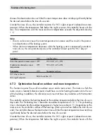
Страница 65: ...controller reacts immediately to room temperature deviations during day or night mode the function block setting HC1 CO1 09 ON must be made The heating is then always switched off as soon as the room...

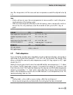
Страница 66: ...tion in room temperature arises We recommend setting Gain to 10 0 Functions WE Configuration Room temperature measurement OFF HC1 CO1 01 ON Outdoor temperature measure ment ON HC1 CO1 02 OFF Flash ada...

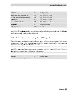
Страница 67: ...ould not be configured as well 6 10 Set point correction using a 0 to 10 V signal The HC1 set points can be corrected in a linear manner within the range between 8 C poten tiometer input 1 V to 8 C po...

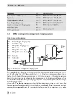
Страница 68: ...ture the control ler tries to build up the flow temperature in the heating circuit for up to five minutes before the storage tank charging pump P3 is activated If the function DHW CO4 16 ON SLP not ON...

Страница 69: ...P3 is switched off after Lag time for storage tank charging pump has elapsed The default settings cause the temperature in the storage tank is to increase by 5 C to reach 60 C when the storage tank te...

Страница 70: ...desired charging temperature DHW day set point Charging temperature boost the controller tries to reduce the flow temperature in the heating circuit for up to fives minutes before the heat exchanger...

Страница 71: ...charging cycle will be used again at the beginning of the next cycle If times of use have been set for DHW heating DHW day set point applies during these times of use Outside the times of use the DHW...

Страница 72: ...s WE Parameter settings Min adjustable DHW set point 40 0 C DHW PA4 01 5 0 to 90 0 C Max adjustable DHW set point 60 0 C DHW PA4 02 5 0 to 90 0 C Hysteresis 5 0 C DHW PA4 03 1 0 to 30 0 C Charging tem...

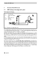
Страница 73: ...T DHW day set point Hysteresis has been exceeded at storage tank sensor S8 In this way circulation losses even for small amounts of tapped hot water are compensated for over the heat exchanger Functio...

Страница 74: ...e DHW temperature to Day DWH set point just while the DHW is being tapping When the tapping is finished the valve closes and the heat exchanger charging pump P1 is switched off after a delay Function...

Страница 75: ...unction block setting DWW CO4 06 ON the heating pump UP1 remains switched on during DHW heating unless certain operating situations occur These situations include for ex ample those when the current f...

Страница 76: ...when they are required at the same time As a result the capacity required for DHW heating needs to be taken from the heating sys tem when great heating loads occur and this until DHW heating has been...

Страница 77: ...eration The function block setting DHW CO4 09 ON allows the temperature at the flow sensor DHW to be monitored In systems without the flow sensor DHW the temperature directly at the storage tank senso...

Страница 78: ...test ends at the specified Stop time of thermal disin fection The Disinfection temperature sustaining time determines how long the disinfection temperature must be maintained within the adjusted time...

Страница 79: ...a storage tank thermostat is used The connection of the fault indication output with DHW CO4 15 ON differs depending on the system Refer to the fold out page Functions WE Configuration Storage tank se...

Страница 80: ...W circuit is automatically switched on only when the heating circuit of the system if one exists is inactive Nevertheless the stor age tank is always recharged to 10 C if the storage tank temperature...

Страница 81: ...flow tempera ture flow temperature of the heating system charging temperature is reduced As a result the primary flow rate is reduced and the return flow temperature falls In systems 2 1 0 and 2 2 0 t...

Страница 82: ...W PA4 07 20 0 to 90 0 C 8 5 Condensate accumulation control Activate the OPEN signal damping function to start up condensate accumulation plants in par ticular to avoid problematic excess temperatures...

Страница 83: ...40 s Three step control ON 2 0 120 s 0 s 45 s DHW CO4 12 ON Gain KP 0 1 to 50 0 Reset time TN 0 to 999 s Derivative action time TV 0 to 999 s Valve transit time TY OPEN 10 to 240 s 8 7 On off control...

Страница 84: ...WE Configuration Three step control ON 2 0 120 s 0 s 45 s HC1 CO1 12 ON Gain KP 0 1 to 50 0 Reset time TN 0 to 999 s Derivative action time TV 0 to 999 s Valve transit time TY OPEN 10 to 240 s Three...

Страница 85: ...systems with supplementary heating circuit without a valve Anl 2 1 0 and 2 2 0 Functions WE Configuration Unlock control loop 1 at S5 OFF 1 HC1 CO1 14 ON Control loop 1 switching state active 0 1 Unlo...

Страница 86: ...ge tank charging Functions WE Configuration Priority for external demand OFF DHW CO4 17 ON 8 10 1 Processing an external demand with a binary signal Regardless of the operating mode for control loop 1...

Страница 87: ...0 10 V at UI1 OFF HC1 CO1 16 ON Primary controller Parameter WE Parameter settings Set point boost of pre control loop 5 C HC1 PA1 15 0 0 to 50 0 C 8 11 Demand requested with a 0 to 10 V signal The c...

Страница 88: ...value outdoor temperature 30 0 to 100 0 C Upper transmission range value outdoor temperature 30 0 to 100 0 C 8 13 Locking the manual level To protect the heating system this function can be used to lo...

Страница 89: ...for error information is displayed The following errors are listed Drying of jointless floors refer to section 6 3 Max charging temp reached refer to section 7 2 Sensor failure refer to section 9 1 Te...

Страница 90: ...associated valve is closed 4 Return flow sensor When the return flow sensor fails the controller continues operation without return flow temperature limitation 4 Room sensor When the room sensor fails...

Страница 91: ...s configured the fault indication output is activated when an error exists Section 5 for the assignment Any errors still appear in the error list Functions WE Configuration Fault indication output OFF...

Страница 92: ...mounting set consists of terminal strips for the wiring and two clamps to lock the con troller housing in place The controller without a base is used for panel mounting 1 Make a cut out of 138 x 92 m...

Страница 93: ...housing are used the degree of protection IP 40 without seal for panel mounting IP 41 with seal for panel mounting cannot be maintained 2 Attach the base housing to the wall using four screws arrows...

Страница 94: ...largest possible cross section Connect the central grounding point and the PE grounding conductor with a cable 10 mm using the shortest route 4 Inductances in the control cabinet e g contactor coils a...

Страница 95: ...s 4 0 to 10 V control output Connect cables with a min cross section of 2 x 0 5 mm 4 Three step on off control outputs Route wires with at least 1 5 mm suitable for damp locations to the terminals of...

Страница 96: ...Electrical connection All ground terminals are connected internally with one another S4 S2 S1 S3 S5 N L M1 LM1 M1 LP P1 1 3 2 Typ 5257 5 Pt 1000 N L Fig 10 Electrical connection for the compact versio...

Страница 97: ...or the standard version All ground terminals are connected internally with one another Flow switch GND Outputs input Type 5257 5 NOTICE If both M1 and M2 outputs are connected to motorized valves we d...

Страница 98: ...are available The interface board required for the memory pen refer to section 12 1 can be ordered with the order no 1402 0321 Retrofitting interfaces 1 Remove the dummy module on the left side of th...

Страница 99: ...COPA TO MEMORY PEN button appears After data transfer has been completed OK Remove pen ap pears If data transfer is not completed successfully Error appears on the screen 12 2 TROVIS VIEW The TROVIS...

Страница 100: ...emperature measurement Not Anl 1 9 0 1 9 1 OFF ON OFF Function inactive ON Return flow temperature measurement and limita tion active 1 0 Function block parameter Limiting factor 0 1 to 10 0 Anl 1 0 1...

Страница 101: ...nly when HC1 CO1 02 ON 120 min Function block parameter Preheating time 0 to 360 min 07 Optimization based on room temperature Not Anl 1 9 0 1 9 1 3 5 0 OFF OFF No optimization ON Optimization active...

Страница 102: ...0 to 600 s Three step control continuous control Gain KP 0 1 to 50 0 Reset time TN 0 to 999 s Derivative action time TV 0 to 999 s Do not change this value Valve transit time TY OPEN 10 to 240 s 13 OP...

Страница 103: ...nction block parameters Range of values 17 Binary demand processing Not Anl 1 9 0 1 9 1 OFF 1 OFF Function inactive ON Binary demand processing active Function block parameter Demand switching state a...

Страница 104: ...ank sensor S8 active Function block can only be selected when DHW CO4 01 ON Anl 1 1 0 1 1 1 2 0 0 2 1 0 Anl 1 2 0 1 6 0 1 6 1 1 6 2 2 2 0 03 Return flow temperature measurement Not Anl 1 1 0 1 1 1 1 2...

Страница 105: ...rse control Only Anl 1 1 0 1 1 1 1 2 0 11 0 0 11 2 0 11 9 0 11 9 1 OFF OFF Function inactive ON Priority by reverse control active only when DHW CO4 09 OFF 2 min 1 0 Function block parameters Delay of...

Страница 106: ...to 10 0 C 14 Thermal disin fection Not Anl 1 9 0 11 9 0 11 9 1 OFF OFF Function inactive ON Thermal disinfection active 3 00 00 h 04 00 h 70 0 C 10 0 C 0 min Function block parameters Day of week for...

Страница 107: ...in DHW circuits without control valve 18 Reserved 19 Scheduled switchover be tween S7 and S8 Not Anl 1 9 0 1 9 1 11 0 0 11 9 0 11 9 1 OFF OFF Function inactive ON Time controlled sensor switchover on...

Страница 108: ...e ON Control when delay decreasing outdoor tempera ture 3 C h Function block parameter Outdoor temperature delay 1 to 6 C h Note The setting of this function block parameter changes the function param...

Страница 109: ...S5 All OFF OFF Function inactive ON Unlock controller at S5 depending on switching state 1 Function block parameters Controller switching state active 0 1 16 Return flow lim itation by PI algorithm O...

Страница 110: ...HC1 CO5 Function Anl WE Comment Function block parameters Range of values 20 21 Reserved 22 Lock manual level All OFF OFF Function inactive ON Manual level locked 110 EB 5610 EN Appendix...

Страница 111: ...ON active room sensor HC1 CO1 02 OFF fixed set point control HC1 CO1 09 ON active flash adaptation All HC1 50 0 C 5 0 to 130 0 C 04 Flow set point night only when HC1 CO1 01 ON active room sensor HC1...

Страница 112: ...ack flow All HC1 10 0 K 0 0 to 50 0 K 09 Outdoor temperature for continuous rated opera tion day All HC1 15 0 C 35 0 to 5 0 C 10 Min flow set point in heating circuit with active binary demand All HC1...

Страница 113: ...DHW set point All DHW 60 0 C 5 0 to 90 0 C 03 Hysteresis Not Anl 1 9 0 1 9 1 11 0 0 11 9 0 11 9 1 5 0 C 1 0 to 30 0 C 04 Charging temperature boost Not Anl 1 9 0 1 9 1 11 0 0 11 9 0 11 9 1 10 0 C 0 0...

Страница 114: ...fitted with a web module Refer to EB 5610 1 EN Web Module and TROVIS MOBILE Web Applica tion PA6 Parameter Anl WE Setting range 01 to 09 Reserved 10 COM reset All 0 0 1 NOTICE If the parameter is swi...

Страница 115: ...57 5 Room Temperature Sensor room panel C 35 30 25 20 15 10 5 0 5 10 862 5 882 2 901 9 921 6 941 2 960 9 980 4 1000 0 1019 5 1039 0 C 15 20 25 30 35 40 45 50 55 60 1058 5 1077 9 1097 3 1116 7 1136 1 1...

Страница 116: ...ep or on off 4 x binary outputs for pumps fault indication or demand or 2 x control signal outputs M1 and M2 three step or on off 3 x binary outputs for pumps fault indication or demand Interfaces 1 s...

Страница 117: ...a Station Operator SAMSON office System code number Function block settings in the configuration level HC1 CO1 DHW CO4 HC1 CO5 01 02 03 04 05 06 07 08 09 10 11 12 13 14 15 16 17 18 19 20 21 22 EB 5610...

Страница 118: ...C Flow temperature point 4 5 0 to 150 0 C Reduced flow temperature point 1 5 0 to 150 0 C Reduced flow temperature point 2 5 0 to 150 0 C Reduced flow temperature point 3 5 0 to 150 0 C Reduced flow...

Страница 119: ...05 Temperature increase for drying of jointless floors 1 0 to 10 0 C day 05 06 Max temperature for drying of jointless floors 2 0 to 60 0 C 05 07 Max temperature sustaining time for drying of jointles...

Страница 120: ...to 90 0 C Function block parameters DHW CO4 03 01 Limiting factor 0 1 to 10 0 06 03 Delay of cancelation due to system deviation 0 to 10 min 06 04 Min flow set point in heating circuit for parallel p...

Страница 121: ...Delay of summer mode active 1 to 3 days 04 03 Latest start date for summer mode User definable 04 04 Delay of heating mode active 1 to 3 days 04 05 Outdoor temperature for summer mode 0 0 to 30 0 C 0...

Страница 122: ...d charging 78 thermal disinfection 78 Day set point 55 Deactivation based on outdoor temperature 60 Deactivation values HC 60 Delayed outdoor temperature adaptation 62 Demand 87 Display brightness 25...

Страница 123: ...inary signal 86 R Remote operation 62 Resistance values 115 Return flow temperature limitation 81 Reverse control 76 S Sensor failure 90 Sensors Pt 1000 62 Set point correction heating circuit 67 Set...

Страница 124: ...124 EB 5610 EN...

Страница 125: ...EB 5610 EN 125...

Страница 126: ...126 EB 5610 EN Key number 1732...

Страница 127: ...rd UI1 S5 UI2 UI1 S4 M2 UO1 UO1 S5 M2 UO1 1 0 1 Compact S5 S4 S5 Standard UI1 S5 UI2 UI1 S4 M2 UO1 UO1 S5 M2 UO1 1 1 0 Standard UI1 S5 UI2 UI1 S8 P3 S7 S4 P3 UO1 UO1 S5 P3 UO1 1 1 1 Standard UI1 S5 UI...

Страница 128: ...SAMSON AG MESS UND REGELTECHNIK Weism llerstra e 3 60314 Frankfurt am Main Germany Phone 49 69 4009 0 Fax 49 69 4009 1507 Internet http www samson de EB 5610 EN 2015 02...

Отзывы: