18
EB 8365 EN
Attachment to the valve
3.4
Attachment to positioner
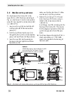
For attachment of the limit switch to the
Type 4763 or 4765 Positioner according to
Fig. 4, a short lever (1) and an intermediate
piece (31) are required as accessories (order
no. 1400-6710).
1. Insert one O-ring (30) into both the left
and the right side of the intermediate
piece (31).
2.
Push the two fillister head screws (33)
through the limit switch and intermediate
piece, and insert them into the positioner.
3. Insert the nuts (32) into the positioner
housing and screw tight the two fillister
head screws (33).
Make sure that the short lever (1) slides
over the pin (16) of the positioner.
4. Replace the vent plug (17) in the posi-
tioner housing with the screw plug in-
cluded in the accessories (order no.
1400-6710).
In exchange, insert the vent plug into the
housing of the limit switch. This ensures
that the degree of protection of the limit
switch corresponds to that of the posi-
tioner.
Î
To achieve degree of protection IP 65, a
check valve (order no. 1790-7408)
needs to be installed in the housing of
the limit switch.
17
A
B
30
31
16
1
31
32
33
NOTICE
Attach the housing cover to the limit switch
ensuring that the vent plug (17) faces
downward after the valve is installed.
Lever with spring
Sectional view A – B
Fig. 4:
Attachment with intermediate piece, e.g. to Type 4765 or Type 4763 Positioner
Содержание 4746
Страница 4: ......
Страница 27: ...EB 8365 EN 27...
Страница 28: ...28 EB 8365 EN...
Страница 29: ...EB 8365 EN 29...
Страница 30: ...30 EB 8365 EN...
Страница 31: ...EB 8365 EN 31...
Страница 32: ...32 EB 8365 EN...
Страница 33: ...EB 8365 EN 33...
Страница 36: ...36 EB 8365 EN...
Страница 37: ...EB 8365 EN 37...
Страница 38: ...38 EB 8365 EN...
Страница 39: ...EB 8365 EN 39...


