16
EB 8365 EN
Attachment to the valve
3.3
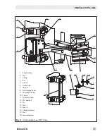
Attachment to Type 3591
Valve
Î
Use the supplied washers for all screw
connections.
1. Fasten the round brackets (1) using the
clamps (3) and nuts (2) lightly onto the
valve yoke.
2. Screw tight the bar (4) using the screws
(5) onto the clamps (3).
3. Fasten the limit switch (6) onto the bar
(4) as described in step 3 of section 3.1.
Use the thread (7) in the bar.
4.
Fasten the mounting bracket (9) using the
screws (10) to the anti-rotation fixture (8)
of the valve.
5. Screw the follower clamp (11) to the
mounting bracket (9) using the nut and
bolt (12).
6. Insert the pin (13) into the oblong hole of
the follower clamp (11). Make sure that
the pin is inserted through the wire strap
of the follower clamp.
7. Thread the nut (14) onto the pin (13).
Place the clamp (16) over the lever (15)
of the limit switch (6).
8. Use the nut (17) to fasten the lever (15)
onto the lever extension (18).
9.
Fasten the other end of the lever exten-
sion (18) to the follower clamp (11).
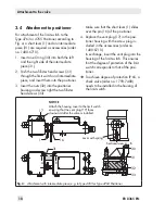
10. Perform alignment.
The following applies concerning attach-
ment:
Î
Perform the alignment in such a way that
the lever (15), lever extension (18) and
oblong hole of the follower clamp (11)
are in line with each other.
Î
After attaching the limit switch, make
sure that the vent plug of the housing
cover faces downward when the valve is
installed.
Содержание 4746
Страница 4: ......
Страница 27: ...EB 8365 EN 27...
Страница 28: ...28 EB 8365 EN...
Страница 29: ...EB 8365 EN 29...
Страница 30: ...30 EB 8365 EN...
Страница 31: ...EB 8365 EN 31...
Страница 32: ...32 EB 8365 EN...
Страница 33: ...EB 8365 EN 33...
Страница 36: ...36 EB 8365 EN...
Страница 37: ...EB 8365 EN 37...
Страница 38: ...38 EB 8365 EN...
Страница 39: ...EB 8365 EN 39...


