


6
Questions?
samsara.com/support
WIRING
VS2 INSTALLATION GUIDE
This section describes the connection of the vision system to standard components. The VS2
features ethernet and Wi-Fi for internet connectivity and supports trigger inputs and outputs from
NPN and PNP devices and lines.
For additional guidance on integrating with both rejection and local control systems consult your Samsara representative.
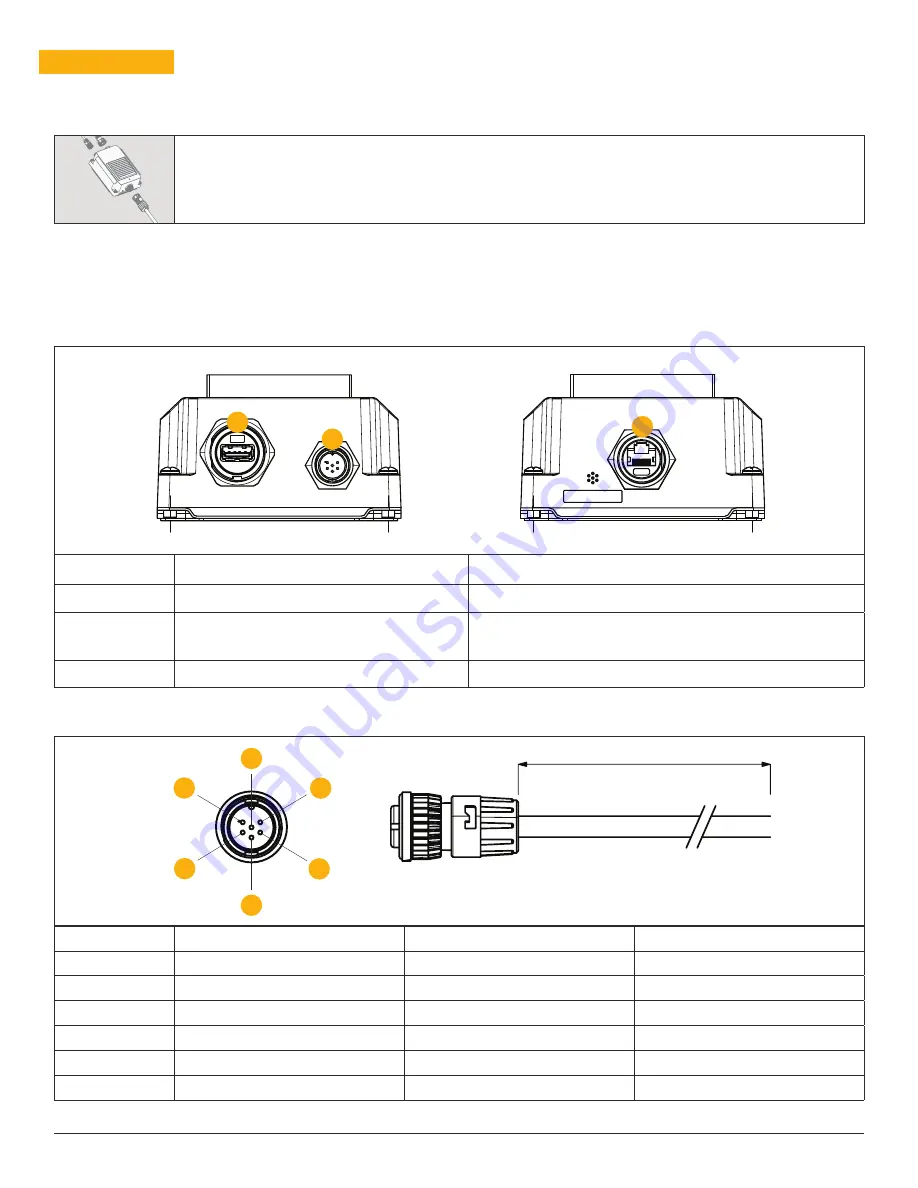
Controller connectors
Connector
Name
Function
1
Camera
Connects the controller to the camera.
2
Power/IO
Connects the breakout cable which provides power as well as
connections to the input trigger and output.
3
Ethernet
Connects the controller to the network.
Breakout cable pin-out
Pin
Signal Name
Wire Color
Voltage Specification
1
Power
Red
12V
2
Ground
Black
—
3
Input Trigger
Green
10 – 30V
4
Input Common
White
10 – 30V
5
Output
Blue
10 – 30V
6
Output Common
Gray
10 – 30V
Connectors and Indicators
1
6
3
1
5
4
2
2
3
5M


