8
853 831 R. 02/20
SAMOA Industrial, S.A. · Pol. Ind. Porceyo, I-14 · Camino del Fontán, 831 · 33392 - Gijón - Spain · Tel.: +34 985 381 488 · www.samoaindustrial.com
2020_02_05-09:30
EN
1.
Take away the air motor from the lowers, as described previously.
2.
Take away the clip (49) and unscrew the nut (50).
3.
Unscrew the cartridge (55) and remove the circlip (58).
4.
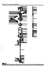
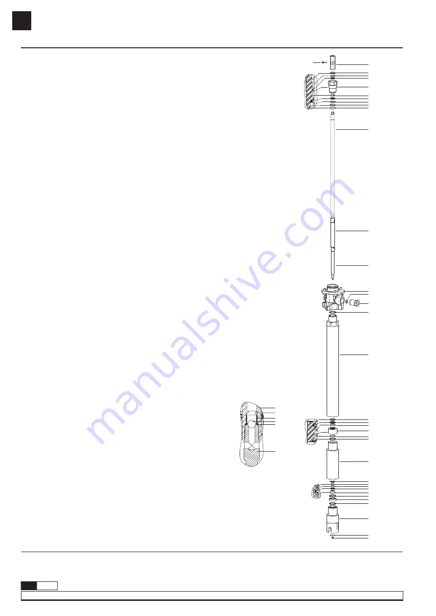
Take away the scraper (52), rings (53) and seals (54, 56), and replace them by new
ones. Ensure the orientation of seals and scraper is as shown in fig 8.
5.
Replace o-ring (59) by a new one.
6.
Take away nut (89) and washer (88).
7.
Take away the assembly consisting of parts (51), (67) and (72) from the lowers.
8.
With the tube (74) secured on a vise, unscrew the tube (87)*.Extract parts (73, 81, 85,
86). Take away circlip (82) from the valve (85) and replace parts (73, 83, 84) by new
ones. Ensure the orientation of seal (84) is as shown in fig 8.
9.
With the tube (74) secured on a vise, unscrew the tube (80)*.
10.
Extract cartridge (77) and replace parts (75, 76, 78, 79).
11.
With the tube (74) secured on a vise, unscrew the pump body (63) and replace seal
(73)*.
12.
Unscrew adapter (65) from the body (63) and replace seal (64).
13.
Re-assembly back all the parts in reverse order*. Chemical thread locker is strongly
recommended for fixing and sealing all joints between tubes and outlet adapter. Also,
metallic seals are used in these joints, so make sure to apply huge torque to deform
them in order to ensure proper sealing of said seals.
14.
A kit with all the lowers seals is available for ordering (534901).
*NOTE:
due to the extreme working conditions of this pump, tubes are factory joint with high
strength chemical sealant and huge tightening torques to deform metallic seals. Therefore, it
is such a complicated task to unscrew the three tubes and screw them back. Heavy duty tools
are needed (i.e. large Stillson wrenches, apropiate grips and vises, blowtorch to melt the
sealant…).
REPAIR AND CLEANING PROCEDURE
LOWER SEALS KIT (FIG. 8)
1.
Lower valve can be accessed disassembling the lowers as described
previously. Kit 534902.
2.
Upper valve: unscrew priming rod (72) from HP piston (67). The valve
can then be replaced/cleaned (fig 9). Kit 534903.
NOTE:
to unscrew primin rod (72) from piston (67), use any of their short
cylindrical surfaces for grabbing (tools, vise, etc). Do not use any of the long
cylindrical surfaces since they are intended for sealing and should not be
scratched/damaged.
CLEANING OR REPLACING THE LOWERS VALVES
Page: 16, 19 and 20.
PARTS LIST / TECHNICAL DATA / DIMENSIONS
Fig. 8
Fig. 9
50
49
52
53
54
55
54
56
57
58
59
51
67
72
63
64
65
73
74
75
67
76
68
78
69
77
70
78
71
72
79
80
81
82
83
84
85
73
86
73
87
88
89


