background image

6

853 831  R. 02/20

 SAMOA Industrial, S.A. · Pol. Ind. Porceyo,  I-14 · Camino del Fontán, 831 · 33392 - Gijón - Spain · Tel.: +34 985 381 488 · www.samoaindustrial.com

2020_02_05-09:30

EN

Fig. 6

21

22

18

15

14

24

Fig. 5

22

24

25

26

27

25

14

28


1.

  Unscrew bolts (24).


2.

  Remove exhaust assembly (22).


3.

  Unscrew the bolts (14) and remove the cap (28).


4.

  Remove the felt (25).


5.

  Remove the felt (27) and deflector (26).


6.

  Remove the bottom felt (25) and replace it with a new one.


7.

  Put back the deflector (26).


8.

  Insert the screws (24) and then a new felt (27). If not in this order, 

it could be tricky to insert the screws.


9.

  Put a new felt (25).


10.

  Put back the cap (28) and its screws (14).


11.

  Ensuring the screws (24) stay into the muffler (22), put said muffler 

on the motor and fix it with said screws.


12.

 It  is  also  available  a  whole  muffler  assembly  kit  (539005),  

with replaces the old one just operating the screws (24).

REPAIR AND CLEANING PROCEDURE

WARNING! 

BEFORE STARTING ANY KIND OF MAINTENANCE OR REPAIR:

• 

DISCONNECT THE COMPRESSED AIR SUPPLY AND OPEN THE VALVE TO 
RELIEVE GREASE PRESSURE. THE PUMP IS ABLE TO STORE 

ULTRA HIGH 

PRESSURE

, SO EXTREME PRECAUTIONS MUST BE TAKEN.

• 

HEAVY WEIGHT EQUIPMENT: BE SURE TO FIX THE PUMP IN A STABLE 
POSITION, USING THE UPPER EYE-BOLT WITH A LIFTER OR SOME STRONG 
GRIPPING DEVICE (I.E. A VISE).

!

SEPARATE THE AIR MOTOR FROM THE PUMP (FIG. 4)


1.

  Use some kind of lifter/support to manipulate and place the pump 

in a vertical and stable position. For instance, both upper eye-bolts 
(1) for lifting/hanging the motor and a vise for gripping the body/
tube (63/74) can be used.


2.

  Take away both protective shields (46) by their bolts (90).


3.

 Ensure the grease oulet valve is open, connect air and carefully 

increase the pressure just until the pump starts to cycle in order to 
get the connecting nut (50) a middle to low position of the stroke. 
Now disconnect the air and make sure the pump is discharged, 
with no internal pressure (grease outlet open).


4.

  Unscrew the 4 bolts (62).


5.

 Now the connecting nut (50) can be unscrewed from the lower 

rod by spinning the whole motor counterclockwise. Warning! The 
lowers get now free from the motor, so make sure the pump tube 
is supported/fixed prior to separating the motor. 

CLEAN THE MUFFLER (FIG. 5)

AIR DISTRIBUTOR (FIG. 6)


1.

  Unscrew the bolts (14) and remove the cap (15).


2.

  Ensuring the screws (24) remain into the muffler (22), unscrew 

them and take away the muffler. Take away the o-ring (21).


3.

 Strike gently with a plastic tool through exhaust side of 

the motor to remove the spool valve (18).


4.

  Replace the spool (18) by a new one with its seals factory 

installed (kit 539006). This is strongly recommended in 
order to ensure the correct assembly of the seals.

1

46

ATEX: periodically clean dust 

deposits in the rod and upper 

packing by removing shields 

(46).

90

49
50
47
63
62

74

Fig. 4

Содержание 533911

Страница 1: ...cal service guide Gu a de servicio t cnico y recambio Part No C d 533911 533921 533910 533920 200 1 RATIO AIR OPERATED GREASE PUMP PM80 2 BOMBA NEUM TICA DE GRASA PM80 RATIO 200 1 9 EN ES ADVERTENCIA...

Страница 2: ...technical specifications is set at 70 C maximum and the maximum friction heating of the pump 25 C Directive part 2014 34 EU Standard part UNE EN ISO 80079 36 2017 ATEX MARKING CAREFULLY READ THE INSTR...

Страница 3: ...perature will depend on that of the grease or ambient and should be taken into account In the presence of explosive atmospheres keep the pump away from it while making service tasks SPECIAL CONDITIONS...

Страница 4: ...lified personnel only When not in use be sure to shut off the air supply to avoid accidents Do not alter or modify this equipment Use only Samoa Industrial S A genuine components Any unauthorized tamp...

Страница 5: ...ase leakage at some point in the circuit Verify and tighten or repair Contamination in the upper valve Disassemble and clean Replace if damaged Contamination in the foot valve Disassemble and clean Re...

Страница 6: ...AIR MOTOR FROM THE PUMP FIG 4 1 Use some kind of lifter support to manipulate and place the pump in a vertical and stable position For instance both upper eye bolts 1 for lifting hanging the motor an...

Страница 7: ...ring 6 and ring 7 and replace them with new ones later 5 Unscrew bolts 44 92 Pull the motor head 13 upwards to free it along with flange 34 6 Take away the gasket 8 and replace its seals 9 and 10 7 U...

Страница 8: ...ended for fixing and sealing all joints between tubes and outlet adapter Also metallic seals are used in these joints so make sure to apply huge torque to deform them in order to ensure proper sealing...

Страница 9: ...s t cnicas se fija en 70 C m ximo y del m ximo calentamiento por fricci n de la bomba 25 C Gb Db nos indica el EPL de la bomba Parte directiva 2014 34 EU Parte norma UNE EN ISO 80079 36 2017 MARCADO A...

Страница 10: ...enerse en cuenta En presencia de atm sferas explosivas realice el mantenimiento de la bomba lejos de la misma Limpie el rea de la bomba y los dep sitos de polvo regularmente cuando trabaje en ambiente...

Страница 11: ...a prevenir accidentes cuando el equipo no est en uso aseg rese la desconexi n de este de la l nea de alimentaci n de aire No altere la integridad del equipo Use componentes originales de Samoa Industr...

Страница 12: ...impurezas Desmonte y limpie V lvula inferior no cierra por impurezas o por deterioro Desmonte y limpie Sustituya en caso de deterioro Fuga de grasa por el orificio testigo en el cuerpo de la bomba 63...

Страница 13: ...no est firmemente sujeto por ejemplo con un elevador puede caerse y provocar da os personales y materiales LIMPIEZA DEL SILENCIADOR FIG 5 DISTRIBUIDOR DE AIRE FIG 6 1 Desenrosque los tornillos 14 y re...

Страница 14: ...ado y desenrosque el casquillo 5 fig 7b 4 Deseche la t rica 6 y el aro 7 y use otros nuevos posteriormente al volver a montar 5 Desenrosque los tornillos 44 92 Tire hacia arriba del cabezal motor 13 h...

Страница 15: ...los bajos tal como se describe anteriormente 2 Retire el clip 49 y desenrosque la tuerca de conexi n 50 3 Desenrosque el cartucho 55 y retire el circlip 58 4 Retire el rascador 52 aros 53 y juntas 54...

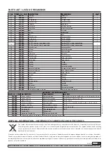
Страница 16: ...3 Exhaust muffler deflector Deflector silenciador 1 27 853607 Central felt Fieltro central 1 28 753106 Exhaust muffler stopper Tapa silenciador 1 29 945728 Plug Tap n 1 30 853602 Motor washer Arandela...

Страница 17: ...w clamp Cable de tierra con pinza 1 PARTS LIST LISTA DE RECAMBIOS REPAIR KIT KIT DE REPARACI N PART NO C D DESCRIPTION DESCRIPCI N IND POS 534901 Lower seals kit Kit juntas bajos 52 2x 53 54 56 59 3x...

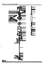
Страница 18: ...18 853 831 R 02 20 SAMOA Industrial S A Pol Ind Porceyo I 14 Camino del Font n 831 33392 Gij n Spain Tel 34 985 381 488 www samoaindustrial com 2020_02_05 09 30 PARTS LIST LISTA DE RECAMBIOS 14 95...

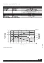
Страница 19: ...CX20 Puerto Autoclave Engineers Medium Pressure para tubo 9 16 rosca 13 16 16 SF562CX20 Air piston diameter Di metro pist n de aire 200 mm 8 Stroke Carrera 100 mm 4 Weight Peso 59 55 kg 130 121 lb Amb...

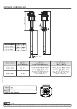
Страница 20: ...TRO D GREASE OUTLET SALIDA DE GRASA 533910 533920 3 4 BSP F Autoclave Engineers Medium Pressure port for 1 4 tube 7 16 20 thread SF250CX20 Puerto Autoclave Engineers Medium Pressure para tubo 1 4 rosc...

Страница 21: ...21 R 02 20 853 831 SAMOA Industrial S A Pol Ind Porceyo I 14 Camino del Font n 831 33392 Gij n Spain Tel 34 985 381 488 www samoaindustrial com 2020_02_05 09 30 NOTES NOTAS...

Страница 22: ...22 853 831 R 02 20 SAMOA Industrial S A Pol Ind Porceyo I 14 Camino del Font n 831 33392 Gij n Spain Tel 34 985 381 488 www samoaindustrial com 2020_02_05 09 30 NOTES NOTAS...

Страница 23: ...23 R 02 20 853 831 SAMOA Industrial S A Pol Ind Porceyo I 14 Camino del Font n 831 33392 Gij n Spain Tel 34 985 381 488 www samoaindustrial com 2020_02_05 09 30 NOTES NOTAS...

Страница 24: ...file Special conditions for safe use specified in the instruction manual EN SAMOA INDUSTRIAL S A Pol Ind Porceyo I 14 Camino del Font n 831 33392 Gij n Spain declara que los siguientes productos cumpl...

Отзывы: