2
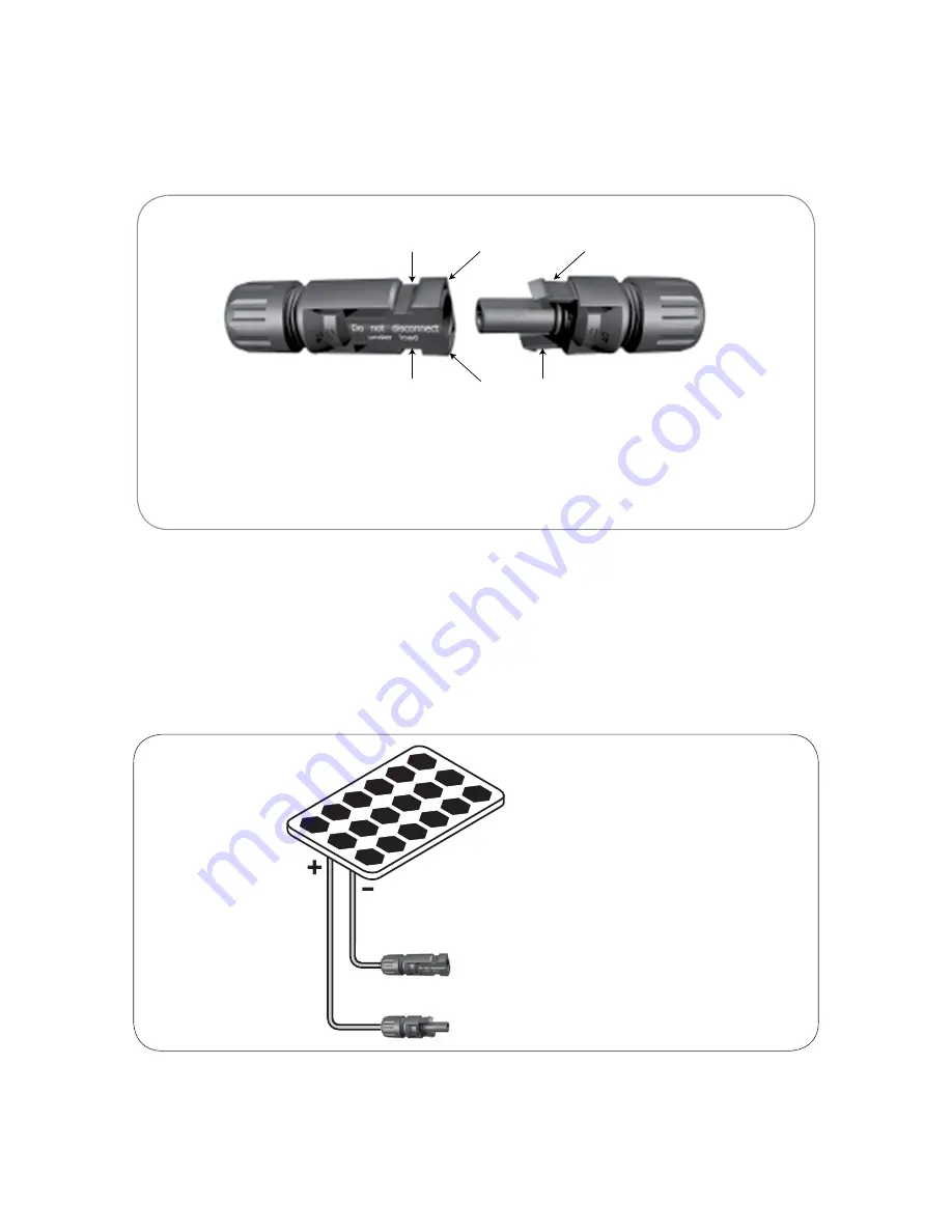
MC4 Connector – Locking Arrangement (Fig. 2)
Two locking tabs (1 of Fig. 2) are provided on the MC4 Female Connector. Two corresponding locking slots (2
of Fig. 2) are provided on the MC4 Male Connector. When the two connectors are coupled, the locking tabs
slide into the locking slots and secure.
To uncouple the two connectors, press the ends of the locking tabs as shown (3 of Fig. 3) to release the
locking mechanism.
1. Locking tabs on the MC4 Female Connector
2. Locking slots on the MC4 Male Connector
3. Press here to release the locking tabs. Make sure that no current is flowing
when uncoupling is attempted.
1
3
3
1
2
2
Fig. 2. Snap-in Locking System
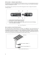
Wire Connections on Solar Panels (See Fig. 3)
Most solar panels come with approximately 3 ft of Positive (‘+’) and Negative (‘-‘) wire. One end of each wire
is connected to the junction box of the panel. In most solar panels (for example, solar panels manufactured
by Samlex Solar), the other end of each wire is terminated with an MC4 connector. The Positive (‘+’) wire has
a Female MC4 Connector and the Negative (‘-‘) wire has a Male MC4 Connector. To extend the length of the
wires of these solar panels for connection to a charge controller, combiner box or grid-connected inverter, an
extension wire is required with corresponding Male and Female MC4 Connectors.
Solar Panel
MC4 Male Connector (Marked “-”)
MC4 Female Connector (Marked “+”)
Fig 3. Solar panel with MC4 Connectors


