


Index revision : A
1
7116
User manual
SAS SAMES Technologies.
13 Chemin de Malacher -
Inovallée - CS 70086 - 38243 Meylan Cedex
Tel. 33 (0)4 76 41 60 60 - Fax. 33 (0)4 76 41 60 90 - www.sames.com
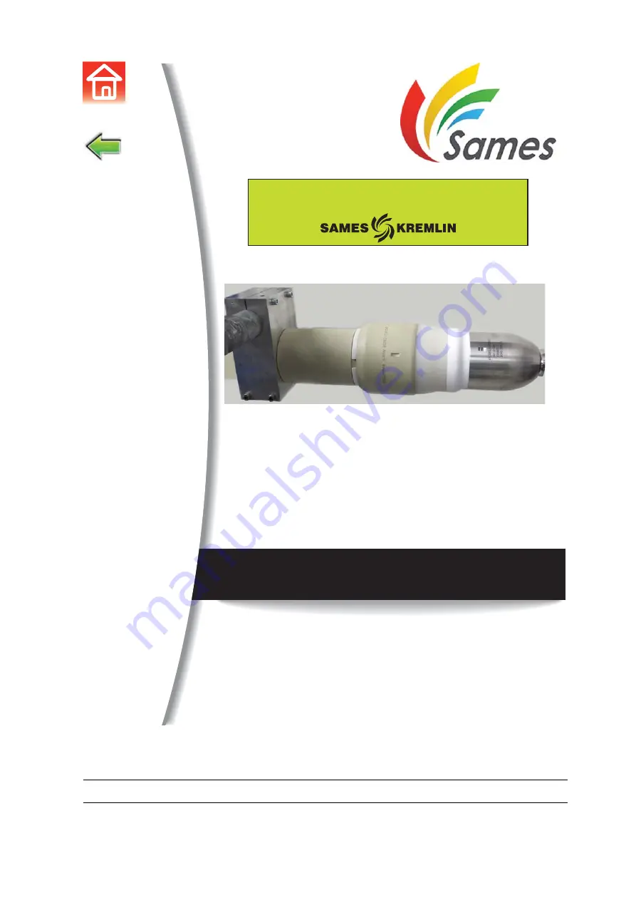
PPH 707 CHEM ICWB M TI
Atomizer
From February 1st, 2017 SAMES Technologies SAS becomes SAMES KREMLIN SAS
A partir du 1/02/17, SAMES Technologies SAS devient SAMES KREMLIN SAS


