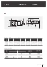
background image

14

Vise

(2) Unclamping
     Turning the handle counter-clockwise will 
     reduce gripping force and unclamp the 
     jaws.  Turn until the regulation pin is in its 
     starting place.  Then the jaws unclamp. 

(2) 풀림작동
    핸들을 반시계 방향으로 돌리면 파악력이
    감소하면서 풀립니다. 레귤레이션 핀이
    제위치에 올때까지 돌려 주십시오.
    그러면 죠가 풀립니다.

IMPORTANT

IMPORTANT

重 要

IMPORTANT

유의사항

!

WARNING

!

WARNING

警 告

If force generates before clamping on the 
workpiece, the vise will malfunction.  Reas-
sembly will be necessary.

Return the handle until the clutch clicks to 
completely engage.

1. Push the handle
2.  Turn the handle 90° in any direction

※ 

To grip by mechanical force, turn 90°

※ 

Gripping force is proportionate to number 

     of handle revolutions.  Please be mindful 
     of reference holes and applicable
     conditions.

!

WARNING

경 고

공작물에 1차 예압을 주지 않은 상태에서 핸들
의 클러치가 빠져 작동하면 증력기구가 제 역할
을 할 수 없습니다. 이때는 수리가 필요합니다.

1. 조절 손잡이를 민다.
2. 방향에 관계없이 90

°

를 돌린다.

 증력식으로 전환하려면 90

°

를 돌리면

    됩니다.

 회전수에 비례하여 파악력이 상승되므로

    가공조건 및 환경에 따라 홈줄(1, 2)을
    확인하고 파악 하십시오.

레귤레이션 핀이 제위치에 올때까지 확실히 핸
들을 돌리십시오.

Fig.4

在没有对工件施加一次预压的状态下扳手
离合器脱离,重力装置不能发挥其作用。
这时需要修理。

(2) 松开时
    将扳手向逆时针方向转动,即可减少
    夹持力而松开。要转到离合器回到自
    己的位置。那么卡爪会松开。

1. 推动调节手柄。
2. 不管什么方向,转动90°。

※  

如果要转为重力式,转动90°即可。

※  

因为夹持力随转速成比例上升,

   根据加工条件和环境确认槽(1、2槽),
   进行夹持。

要转动扳手,直到离合器回到自己的位
置。

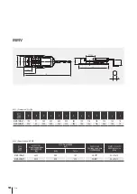
4-3 Using the switch    

       over device (MMV)

4-3 切换装置使用方法
    (MMV)

4-3 절환장치의 사용방법

       (MMV)

Содержание VS

Страница 1: ...rstand DANGER WARN ING items in this maunal before operating the vise Please keep this manual by your side for answers to any questions you may have and to check IMPORTANT Standard Machine Vise Instru...

Страница 2: ......

Страница 3: ...ol which emphasizes important information Warning term DANGER WARNING CAUTION IMPORTANT Indicates an imminently hazardous situation which if not avoided will result in death or serious injury These wa...

Страница 4: ...4 Vise 1 7 2 10 2 1 10 2 2 10 3 11 4 12 4 1 12 4 2 12 4 3 MMV 14 5 15 6 16 7 17 8 19...

Страница 5: ...ummary 10 2 1 Model coding 10 2 2 Construction and operation 10 3 Mounting 11 4 Precautions 12 4 1 Adjusting stop pin 12 4 2 Workepiece 12 4 3 Using the switch over device MMV 14 5 Maintenance and ins...

Страница 6: ...6 Vise 1 7 2 10 2 1 10 2 2 10 3 11 4 12 4 1 Lock pin 12 4 2 12 4 3 MMV 14 5 15 6 16 7 17 8 19...

Страница 7: ...orque specifications are used workpiece may be thrown from the chuck Incorrect Correct Danger by discharge of chuck or workpiece in case of damaging of vise Please read this manual before operating th...

Страница 8: ...e influence lowers judgment and increases likelihood of accident Loose clothing may be caught in the machine NO Alcohol Drugs NO NO L2 L1 2 L2 L1 2 2 The height of the workpiece should be lower than t...

Страница 9: ...ipping workpiece make sure your hand is clear from the gripping area Never attempt to apply excessive force and shock to handle Thoroughly clean the vise The vise may fall and cause injury Vise or wor...

Страница 10: ...compresses the disc spring to create force Depending on application you can adjust the vise to use as a general machine vise VS MMV Standard machine vise Mechanical machine quick vise VS 150 Fig 1 VS...

Страница 11: ...and sharp edge If the flaw or sharp edge are found repair them with oil stone etc before mounting 3 Carefully position when using T groove 4 Securely fix the vise on the machine tool with body bolt 1...

Страница 12: ...otation The stop pin can be adjusted accordingly to jaw width 1 2 CAUTION CAUTION CAUTION Type Widened length 1 2 3 VS 0 100mm 98 200mm 198 300mm MMV 0 115mm 110 230mm 225 350mm 1 2 3 Wodened length F...

Страница 13: ...to the work piece Not enough clamping depth Use as much depth as possible Unilateral clamping Clamp concentrically Lower part of workpiece is not clamped and in result is lifting Use claw jaws R The...

Страница 14: ...mping on the workpiece the vise will malfunction Reas sembly will be necessary Return the handle until the clutch clicks to completely engage 1 Push the handle 2 Turn the handle 90 in any direction To...

Страница 15: ...sliding surface 100mm For 100 mm 100mm 0 015 0 010 2 T The Squareness between guideway of T slot which is bottom of body and Clamping face T 0 015 0 020 3 The parallelism between each clamping face 0...

Страница 16: ...MMV Broken force mechanism MMV MMV Replace disc spring or clean and reassemble booster assembly Poor accuracy Incorrect mounting Page 11 Follow the recommended mounting method Page 11 Page 11 Mounting...

Страница 17: ...200 8 57 5 20 5 SB 200T 36 x 20 x 12 VS 250 10 110 0 36 5 SB 250T 36 x 20 x 12 Type A B C a b c d e f g h i j k VS 150 6 150 45 110 470 440 320 288 245 220 180 115 45 283 18 VS 175 7 175 50 132 547 51...

Страница 18: ...g key size mm Body Table MMV 150Q 6 4 400 56 0 16 0 VS 175T 34 x 16 x 10 MMV 200Q 8 6 500 94 0 23 0 VS 200T 36 x 20 x 12 Type A B C a b c d e g h i j k MMV 150Q 6 150 51 300 800 620 200 240 133 116 12...

Страница 19: ...1 7 Guider 2 8 Stop collar 1 9 Mounting bolt 2 No Name Q ty 10 Key 2 11 Spring pin 1 12 Hex socket head bolt 2 13 Hex socket head bolt 2 14 Hex socket head bolt 2 15 Hex Nut 2 16 Flat washer 2 17 Hex...

Страница 20: ...1 No Name Q ty 23 Disc spring washer 6 24 Name plate 1 25 A K A K Pin A K 1 26 Booster spring 2 27 Knob 1 28 Hex socket head bolt 2 29 Key 2 30 Stopper 1 31 Mounting bolt 2 32 Hex Nut 2 33 Washer 2 34...

Страница 21: ......

Страница 22: ......

Страница 23: ......

Страница 24: ...st e d P ro d u kt io n u b er w ac h t B au ar t g ep ru ft s ISO 9001 2008 V S M M V VIse VS MMV Instruction Manual VS MMV Samchully Machinery 405 820 99 TEL 82 32 822 4811 FAX 82 32 822 4377 405 82...

Отзывы: