Operating manual
Rear disc mowers with central suspension
- with hydro-pneumatic or spring suspension
- 3 2 -
ATTENTION:
The articulated telescopic shafts should always be connected with
the unidirectional right clutch end to the mower.
5.8. Changing the mower position from transport to operating position.
•
open the shut-off valve on the actuator (Pict 13),
•
lower the mower on the TPH of the tractor so that the pins of the suspension frame are at
a minimum of 400 mm above the ground (Pict 14),
•
make sure that the space where the mower will be opened is unobstructed and free of people,
•
pull the line enough to release the locking lever Z (Pict 12) and engaging the external hydraulic
valve on the tractor and the hydraulic hoist of the tractor, position the cutting unit into
a horizontal position,
•
using the lever of the external hydraulic system of the tractor lower the cutting unit so that as it
gets closer to the ground it slows down,
•
release the line of the lock, lower the mower until the load reducing chain is taut. If the pins of
the mower's suspension are lower than 40 cm from the ground (Pict 18b), chain length should
be reduced,
•
unlock the coping tie. See label 26 page 23,
•
using the upper regulated tie G (Pict 9) adjust to the required cutting height. Extending the tie
G increases cutting height and shortening it decreases it,
•
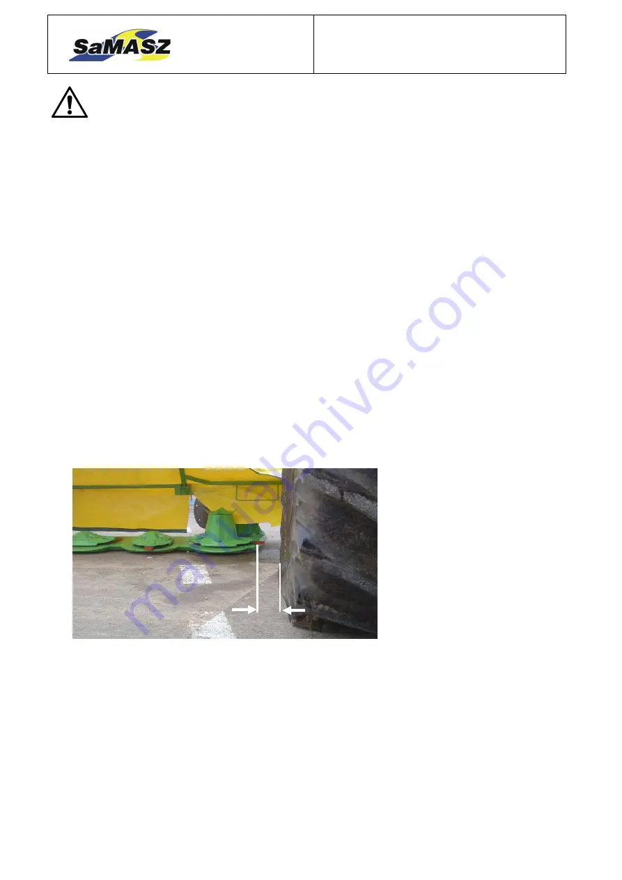
depending on the tractor used the mower should be connected to the three-point hitch so that
the distance Y, the distance between the interior cutting disc and the tires of the tractor, is from
0 to 10 cm with KT 260 H. With KT 300 H the distance Y should be from 30 to 40 cm and
with KT 340 H from 50 to 60 cm.
Pict 15. Side positioning of the mower in relation to the tractor.
Y
With KT 260 H
Y = from 0 to 10 cm
With KT 300 H
Y = from 30 to 40 cm
With KT 340 H
Y = from 50 to 60 cm


