6 Troubleshooting
6-2
SAM4S ER-900/SPS-300 SERIES
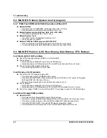
6-3 MAIN B’D Problem (System boot & program)
6-3-1 PGM Flash ROM (A29L1600UV) problem of Main B’D
Related RESET
→
Check the reset IC (AME8500, U5) & reset time (150 ~ 270ms)..
→
Check related circuit & component whether short or not
Related System signals (Address, Data, nCE, nOE, nWE)
→
Check these signals whether it short / open.
Related System Clock
→
Check the crystal, if it operates correctly or not.
→
Clock frequency is 12MHz.
Related PGM Flash ROM program (A29L1600UV)
→
If the boot program is erased during servicing, boot error is occurred.
→
You should replace the flash ROM with programmed new flash ROM.
6-4 MAIN B’D Problem (LCD, Rear Display, Data Memory, RTC, Battery)
6-4-1 Back-light of LCD problem
Check the back-light voltage (VDD5V) on LCD Joint B’D.
Check
harness
→
Harness between Main B’D and LCD Joint B’D (22-pin).
→
Harness between LCD Module and LCD Joint B’D (wire harness 22-pin or 16-pin).
Check the signal (Back-light on/off signal)
→
Check this signal whether it short / open.
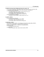
6-4-2 Display of LCD problem
Check the LCD TTL signals on Main B’D.
→
Check the reset signal of AME8500 (U5) output.
→
Check the MCU(LPC2470, U6) and the transceiver (74ACT245, U13) output LCD signals
(R/W and CE#1~#3, EN, data, D/I, etc.)
→
Measure these signals and check whether it short/open or not
Check
harness.
→
Harness between Main B’D and LCD Joint B’D (22-pin).
→
Harness between LCD Module and LCD Joint B’D (Wire harness 22-pin or 16-pin).
Check the voltage VDD50V on the LCD Joint B’D. This voltage is used for LCD Module logic.
6-4-3 Rear Display(FND) problem
Operation Fail
→
Performs the Rear Display(FND) test at H/W test mode.
→
Check the harness between Rear Display B’D and LCD Joint B’D. (FFC harness 17-pin).
→
Check the harness between LCD Joint B’D and Main B’D. (Wire harness 18-pin).
→
Check the MCU(LPC2470, U6) output FND signals.(Segments, Digits)
→
Check related circuit & component on the LCD Joint B’D whether short or not.
Содержание ER-900 Series
Страница 38: ...5 Maintenance and Adjustment 5 2 SAM4S ER 900 SPS 300 SERIES MEMO ...
Страница 78: ...7 Exploded View and Parts List 7 34 SAM4S ER 900 SPS 300 SERIES MEMO ...
Страница 79: ...SAM4S ER 900 SPS 300 SERIES 8 1 8 PCB Layout and Parts List 8 1 Main PCB ...
Страница 84: ...8 PCB Layout and Parts List 8 6 SAM4S ER 900 SPS 300 SERIES 8 2 I F PCB ...
Страница 90: ...8 PCB Layout and Parts List 8 12 SAM4S ER 900 SPS 300 SERIES 8 7 OPTION I F 232 USB PCB ...
Страница 94: ...8 PCB Layout and Parts List 8 16 SAM4S ER 900 SPS 300 SERIES MEMO ...
Страница 95: ...SAM4S ER 900 SPS 300 SERIES 9 1 9 Wiring Diagram 9 1 Main PBA Block Diagram ...
Страница 108: ...10 Block Diagram 10 2 SAM4S ER 900 SPS 300 SERIES MEMO ...
Страница 130: ...11 22 SAM4S ER 900 SPS 300 SERIES MEMO ...
Страница 132: ...ⓒ Shin Heung Precision MAY 2011 Printed in KOREA V1 0 Code No JK68 XXXXXA ...

