
4 Disassembly and Assembly
4-4
SAM4S ER-900/SPS-300 SERIES
4-2 Disassembling the Case Lower Block
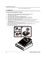
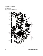
4-2-6 Ass’y Printer(1-Station/ 2-Station, Without A/C)
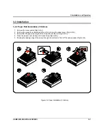
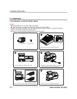
1. Open the ASS'Y COVER PRINTER(A) and lift it off. (Page7-1)
2. Separate the ASS'Y CASE UPPER(C) from the ASS'Y CASE LOWER(F). (Page7-1)
3. Push up the KNOB-RELEASE (E3) and then open the HOUSING CLAM_2M(E6). (Page7-14)
4. Remove two screws(E9) from the PMO-HOLDER PRINTER(E10). (Page7-14)
5. Remove a screw(E7) from the Printer(E8) and then remove the FPC(pp) from the JOINT-Board(E14).
(Page7-14)
6. Separate the ASS'Y PRINTER(E8) from the ASS'Y PAPER-SUPPLY(E23). (Page7-14)
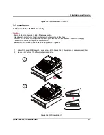
4-2-7 Ass’y Spool Motor
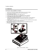
1. Open the ASS'Y COVER PRINTER(A) and lift it off. (Page7-1)
2. Separate the ASS'Y CASE UPPER(C) from the ASS'Y CASE LOWER(F). (Page7-1)
3. Separate the ASS'Y PAPER SUPPLY from the ASS'Y CASE LOWER(F).( Reference:4-2-1~4)
4. Separate the harness(aa) of the ASS'Y SPOOL MOTOR(E24) from the JOINT-B/D(E14). (Page7-14)
5. Remove two screws(E25) from the ASS’Y PAPER SUPPLY(E23). (Page7-14)
6. Separate the ASS’Y HOLDER MOTOR(E24) from the ASS’Y PAPER SUPPLY(E23). (Page7-14)
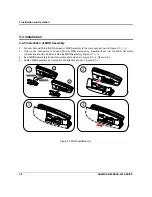
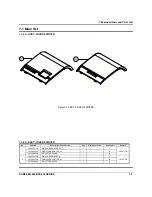
4-2-8 Ass’y Dallas Key or Cover-Dummy
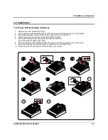
1. Separate the Harness(p) of the ASS’Y DALLAS KEY(F41~44) from the MAIN BOARD(F6). (Page7-22)
2. Lift up the ASS'Y DALLAS KEY(F41~43) or Cover Dummy(F44). (Page7-22)
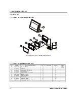
4-2-9 Ass’y MSR
1. Separate the ASS'Y CASE UPPER(C) from the ASS'Y CASE LOWER(F). (Page7-1)
2. Separate harness(q) and ground(r) from the MAIN BOARD(F6). (Page7-22,25)
3. Push the two hooks in the opposite direction from IPR-BRKT MSR(F19) and separate the ASS’Y MSR(G).
(Page7-22)
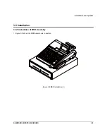
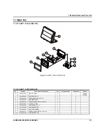
4-2-10 Ass’y Main PBA
1. Separate the fourteen harnesses(j,k,m,n,d,pp,s,q,bb,e,f,i.h.p) from the MAIN BOARD(F6).(Page 7-22)
2. Remove five screws(F5) and then separate the MAIN BOARD(F6) from ASS’Y CASE LOWER(F).
(Page7-22)
4-2-11 Ass’y I/F PBA
1. Separate the three harnesses(u,m,n) from the I/F BOARD(F21).(Page 7-22)
2. Remove screws(F13) and then separate the LAN BOARD(F14).(Page 7-22)
3. Remove two screws(F26) and then separate the OPTION BOARD(F25).(Page 7-22)
4. Remove three screws(F15) and then separate the I/F BOARD(F21) from ASS’Y CASE LOWER(F).
(Page7-22)
Содержание ER-900 Series
Страница 38: ...5 Maintenance and Adjustment 5 2 SAM4S ER 900 SPS 300 SERIES MEMO ...
Страница 78: ...7 Exploded View and Parts List 7 34 SAM4S ER 900 SPS 300 SERIES MEMO ...
Страница 79: ...SAM4S ER 900 SPS 300 SERIES 8 1 8 PCB Layout and Parts List 8 1 Main PCB ...
Страница 84: ...8 PCB Layout and Parts List 8 6 SAM4S ER 900 SPS 300 SERIES 8 2 I F PCB ...
Страница 90: ...8 PCB Layout and Parts List 8 12 SAM4S ER 900 SPS 300 SERIES 8 7 OPTION I F 232 USB PCB ...
Страница 94: ...8 PCB Layout and Parts List 8 16 SAM4S ER 900 SPS 300 SERIES MEMO ...
Страница 95: ...SAM4S ER 900 SPS 300 SERIES 9 1 9 Wiring Diagram 9 1 Main PBA Block Diagram ...
Страница 108: ...10 Block Diagram 10 2 SAM4S ER 900 SPS 300 SERIES MEMO ...
Страница 130: ...11 22 SAM4S ER 900 SPS 300 SERIES MEMO ...
Страница 132: ...ⓒ Shin Heung Precision MAY 2011 Printed in KOREA V1 0 Code No JK68 XXXXXA ...