


4 Disassembly and Assembly
4-2
SAM4S ER-5200 Series
4-2 Disassembling the Case Lower Block
4-2-1 Ass’y Auto Cutter
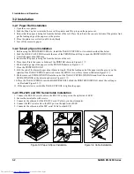
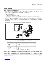
1. Open the COVER PRINTER(A) and lift it off. (Page9-1,9-2)
2. Remove the screw(D-1) and separate the GROUND(a-2,
ⓨ
) from the HOLDER CUTTER(D-19). (Page9-12)
3. Remove the two screws(E-48) on the ASS'Y CASE LOWER(E). (Page9-1,9-2,9-6)
4. Separate the harness(D-16) from the SUB PRT CONN BOARD(C-38). (Page9-8, 9-12)
5. Lift up the ASS'Y CUTTER(D). (Page9-1,9-2)
4-2-2 Ass’y Printer (Receipt & Journal)
1. Open the COVER PRINTER(A) and lift it off. (Page9-1,9-2)
2. If you have the ASS'Y CUTTER(D), first separate it. (Page9-1,9-2)
3. Separate the GROUND(
ⓐ
or
ⓑ
) from the PAPER SUPPLY(C-37). (Page9-8)
4. If you don't have the ASS'Y CUTTER(D), remove the screw(C-42) from the PAPER SUPPLY (C-37) and
lift up the COVER FRONT(C-41). (Page9-8)
5. Remove the four screws(E-1: 4EA or E-4:4EA) from the CASE LOWER(E-38). (Page9-6)
6. Separate the ASS'Y PRINTER(RECEIPT & JOURNAL) from the ASS'Y CASE LOWER(E). (Page9-6)
4-2-3 Ass’y Spool Motor
1. Separate the harness(
ⓙ
) of the ASS'Y MOTOR SPOOL(E-11) from the SUB POWER BOARD(E-18). (Page9-6)
2. Remove the screw (E-12) on the ASS'Y CASE LOWER (E) and separate the ASS'Y HOLDER SPOOL
(E-10) from the ASS'Y CASE LOWER(E). (Page9-6)
3. Remove the screw (E-7) on the HOLDER SPOOL(E-10) and separate the ASS'Y GEAR SPOOL(E-8).(Page9-6)
4. Separate the GEAR SPOOL (E-8) and the RUBBER SPOOL(E-6) from the ASS'Y GEAR SPOOL(E-8).(Page9-6)
5. Remove the two screws (E-9) from the HOLDER SPOOL(E-10) and separate the ASS'Y MOTOR SPOOL(E-11).
(Page9-6)
4-2-4 Ass’y Clerk Key
1. Lift up the ASS'Y CLERK KEY(E-42) and the COVER CLERK KEY(E-43) or COVER FRONT
(E-43) from the ASS'Y CASE LOWER(E).(Page9-6)
4-2-5 Ass’y Main PBA and I/F PBA
1. Separate the nine harnesses(
ⓖ
,
ⓘ
,
ⓟ
,
ⓠ
,
ⓕ
,
ⓡ
,
ⓧ
,
ⓦ
,
ⓢ
,
ⓣ
) and remove the four screw(E-40). Lift up the
MAIN BOARD(E-41).(page9-6)
2. Remove the screw(E-27) and separate the GROUND(
ⓒ
) from the GROUND PLATE(E-32) and the two harnesses
(
ⓡ
,
ⓧ
).(page9-6).
3. Remove the three or two screws(E-21) and lift up the SUB I/F BOARD(E-22). (page9-6)
4-2-6 Ass’y Power PBA, Power S/W PBA and Transformer PBA
1. Separate the five harnesses(
ⓙ
,
ⓛ
,
ⓗ
,
ⓟ
,
ⓠ
) and remove the five screw(E-17). Lift up the POWER BOARD(E-18).
(Page9-6).
2. Separate the three harnesses(
ⓚ
,
ⓜ
,
ⓝ
) and remove the two screws(E-34). (Page9-6)
3. Lift up the SUB POWER S/W BOARD(E-35). (Page9-6)
4. Separate the two harnesses(
ⓚ
,
ⓛ
) and remove the two screws(E-15). (Page9-6)
5. Lift up the TRANS POWER(E-16). (Page9-6)
Downloaded from
www.Manualslib.com
manuals search engine


