
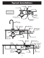


6
Electrical
GENERAL INSTRUCTIONS
Dual voltage disposers are shipped from the factory NOT
connected for a specific voltage. Please refer to the wiring
diagrams on the disposer junction box cover. When
connecting single phase disposers to a reversing control,
refer to the diagram supplied with the control. Salvajor
disposer cutting elements are designed to operate in
either direction.
Use water tight conduit and fittings to make connections.
Caution: Be careful not to pinch wires when replacing junction
box cover.
For new installations, an approved control will need to be
mounted in the dish table with an optional bracket. Power
will have to be run to a solenoid for incoming water.
NOTE:
The RESET button is located on the bottom of the disposer.
TEST PROCEDURE
1.
Check to be sure the disposer cutting teeth are free of
foreign objects.
2.
Turn the disposer on and determine that the cutting
elements rotate freely and that water flows automatically.
3.
Check the mounting assembly and plumbing connections
for leaks.
4.
If disposer fails to operate:
A.
Turn off power.
B.
Check wiring connections.
C.
Determine if the RESET button has tripped.
Reset by hand only.
DANGER:
If disposer stops, DO NOT look for the cause until the
starting control is turned OFF and the power is turned OFF.
Consult Operating Instructions.
Model 200
115 Volts
1 Phase
24.0 Amps
208 Volts
1 Phase
12.1 Amps
230 Volts
1 Phase
12.0 Amps
208 Volts
3 Phase
6.6 Amps
230 Volts
3 Phase
6.0 Amps
460 Volts
3 Phase
3.0 Amps
Model 300
208 Volts
3 Phase
8.8 Amps
230 Volts
3 Phase
8.0 Amps
460 Volts
3 Phase
4.0 Amps
Model 500
208 Volts
3 Phase
13.8 Amps
230 Volts
3 Phase
12.5 Amps
460 Volts
3 Phase
6.3 Amps
Model 750
208 Volts
3 Phase
19.8 Amps
230 Volts
3 Phase
18.0 Amps
460 Volts
3 Phase
9.0 Amps
Model 75
115 Volts
1 Phase
17.8 Amps
208 Volts
1 Phase
9.9 Amps
230 Volts
1 Phase
9.0 Amps
208 Volts
3 Phase
4.2 Amps
230 Volts
3 Phase
4.0 Amps
460 Volts
3 Phase
2.1 Amps
Model 100
115 Volts
1 Phase
18.6 Amps
208 Volts
1 Phase
10.2 Amps
230 Volts
1 Phase
9.3 Amps
208 Volts
3 Phase
4.9 Amps
230 Volts
3 Phase
4.5 Amps
460 Volts
3 Phase
2.3 Amps
Model 150
115 Volts
1 Phase
22.9 Amps
208 Volts
1 Phase
11.8 Amps
230 Volts
1 Phase
11.6 Amps
208 Volts
3 Phase
6.2 Amps
230 Volts
3 Phase
5.6 Amps
460 Volts
3 Phase
2.6 Amps
Model 75
(
3
⁄
4
HP)
Model 100
(1 HP)
Model 150
(1
1
⁄
2
HP)
Model 200
(2 HP)
Model 300
(3 HP)
Model 500
(5 HP)
Model 750
(7
1
⁄
2
HP)
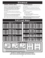
Full Load Amps
MAKE ALL INSTALLATIONS IN ACCORDANCE
WITH LOCAL AND NATIONAL ELECTRICAL CODES.
WIRING DIAGRAMS
5
L 2
L 1
J
2
1
4
8
3
L 2
L 3
L 1
2
3
1
8
9
7
5
6
4
11
12
10
L 2
L 3
L 1
2
3
1
8
9
7
5
6
4
11
12
10
SINGLE PHASE 115 VOLT
5
J
2
8
3
1
4
L 2
L 1
SINGLE PHASE 208 VOLT
5
J
2
8
3
1
4
L 2
L 1
SINGLE PHASE 230 VOLT
3 PHASE 208/230 VOLT
TO REVERSE ROTATION: Interchange #5 & #8 (Single Phase Only)
USE CONTROL PANEL WIRING DIAGRAM when using Salvajor Controls
(Models ARSS, ARSS-LD, ARSS-2 or MRSS) (Single Phase Only)
3 PHASE 460 VOLT


