OWNER’S MANUAL V.102021 ENGLISH
M-9530 ELLIPTICAL KOR
This manual can be downloaded on
www.salter.es
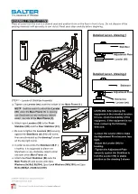
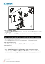
STEP 10– Handlebar Decoration Cover Assembly
Attach the
Front Handlebar Decoration Cover (52)
and the
Rear Handlebar Decoration Cover (53)
to the
Upright Post (46)
and secure with 4pcs
Screws (M4x20mm)(119)
and 3pcs
Bolts (M5xp0.8x15mm)(127)
.
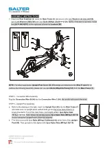
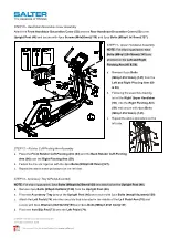
STEP 11– Upper Handlebar Assembly
NOTE:
For shipping purpose, 8pcs
Bolts (M8×p1.25×16mm) (141)
are
attached on the
Left and Right
Pivoting Arm (60 & 59).
a. Remove 8 pcs
Bolts
(M8×p1.25×16mm) (141)
from the
Left and Right Pivoting Arm (60
& 59).
b. Following the assembly drawing,
insert the
Right Upper Handlebar
(55)
onto the
Right Pivoting Arm
(59)
and secure with 4pcs
Bolts
(M8×p1.25×16mm) (141).
c. Repeat the above procedure on the
left side.
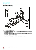
STEP 12 – Rotator Cuff-Pivoting Arm Assembly
a. Place the
Front Rotator Cuff-Pivoting Arm (63)
and the
Back Rotator Cuff-Pivoting
Arm (64)
over the
Right Pivoting Arm (59).
b. Fasten the Covers together with the 4pcs
Bolts (M5Xp0.8X15mm)(127).
c. Repeat the above same procedure on the left side.
STEP 13– Accessory Tray & Pedal Assembly
NOTE:
For shipping purpose, 2pcs
Bolts (M5xp0.8x25mm)(128)
are attached on the
Upright Post (46).
a. Remove 2pcs
Bolts (M5xp0.8x25mm)(128)
from the
Upright Post (46).
b. Place the
Accessory Tray (51)
on the
Upright Post (46)
and secure with 2pcs
Bolts (M5xp0.8x25mm)(128)
.
c. Attach the
Left Pedal (74)
onto the iron plate that is located in the middle of the
Left Pedal Arm (70)
and
secure with 4pcs
Washers (8x19x2.0t)(160)
and 4pcs
Bolts (M8xp1.25x15mm)(131)
.
d. Place the
Non-Slip Pad (73)
onto the
Left Pedal (74)
.


