3
Pegasus Floor Scale Installation Guide
Calibration
For the indicator to function properly, the signals reaching the indicator must
be identical no matter where a weight is placed on the scale. Getting these
signals to match is called corner balancing the scale.
Your goal is to get the readings from the weight sensors to match. You do
not have to get the correct weight reading at this point. That is taken care of
when you calibrate your indicator.
This scale was corner balanced at the factory, but in a new installation it is
required that corner balancing and calibration be checked to ensure installa-
tion accuracy.
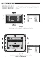
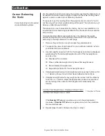
One potentiometer affects one weight sensor. You balance the weight
sensors by adjusting the corresponding potentiometer in the junction box
according to the steps listed on the next page.
1. Remove the junction box cover to access the potentiometers.
2. To capture the value of internal zero for your particular indicator, refer to
your indicator's Service Manual.
3. Use test weights equal to 20-25% of full capacity and obtain a displayed
weight value for the test weight applied to each of the four weight sen-
sors, like this:
3a. Disable AZT on indicator.
3b. Place certified test weight directly above first weight sensor.
3c. Record displayed weight value.
3d. Repeat steps 3b and 3c for each weight sensor.
4. If displayed weight values for all weight sensors equal each other, within
+/- 1 division, proceed now to
Final Span Calibration
instructions.
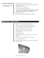
5. If displayed weight value for any weight sensor varies from the others by
more than +/- 1 division, adjust the appropriate junction box potentiom-
eter by turning it the number of 360 degree turns indicated by this
formula:
If the
Number Of Turns
is a positive value, turn the potentiometer
clockwise. If
Number Of Turns
is a negative value, turn the potentiom-
eter counterclockwise.
6. Repeat steps 3b and 3c followed by step 4 or step 5.
Corner Balancing
the Scale
Corner balancing is not required
on precalibrated systems.


