


2
Pegasus Floor Scale Installation Guide
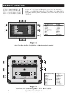
Interface Connections
Figure 2
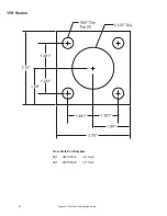
Junction box and wiring table - stainless steel scales
R2 is the corner balance for TB1.
R6 is the corner balance for TB2.
R10 is the corner balance for TB3.
R14 is the corner balance for TB4.
W-T Wire Color
Signal
Green
+Excitation
Yellow
+Sense
White
+Signal
Orange/White
Shield
Red
-Signal
Blue
-Sense
Black
-Excitation
Remove the access plate and the junction box cover plate. Attach the
leads of the indicator interface cable to TB5 in the junction box per Figure
2. On precalibrated systems, this cable is preinstalled and this step is not
necessary.
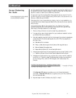
Figure 3
Junction box and wiring table - mild steel scales
W-T Wire Color
Signal
Green
+Excitation
Yellow
+Sense
White
+Signal
Orange/White
Shield
Red
-Signal
Blue
-Sense
Black
-Excitation


