19
L
N
L1
L
N
L2
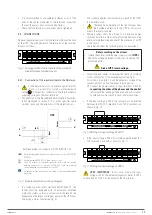
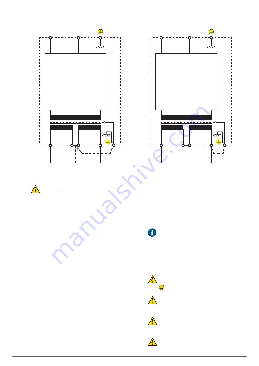
Standard UPS or B1
(a)
120 V
120 V
L
N
L1
L
L2
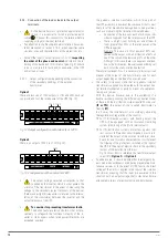
Standard UPS or B1
(a)
240 V
Option 1
Option 2
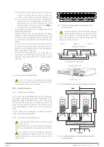
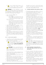
Fig. 14.
Connection options of the UPS’ outputs
WARNING!
•
Follow all of the instructions related to device connection,
startup and shutdown indicated in the instruction manual of
the standard device.
•
Before connecting a battery module to a UPS, check that
the voltage of both, shown on the back of each unit next to
the respective connectors, is the same.
•
It is necessary to install a bipolar circuit breaker or another
device between the UPS and the battery module.
•
Do not attempt to modify the standard model for conversion
as B1, external batteries with more powerful charger. Any
alteration of the device not only
invalidates the warranty,
but also represents a major safety hazard for people
and property
because of the possibility of electric shock,
explosion or fire.
•
Do not connect the internal battery pack of the standard
model to an external battery module. The type of battery
and/or voltage may be different.
If they are connected
together, there is a risk of electric shock or fire!
.
•
For systems in parallel, it will be necessary to repeat the
connections that go from the panel to each device.
Whenever there are discrepancies between the labelling
and the instructions in this manual, the former must take
precedence.
•
With regard to the protection to be placed at the exit of the
distribution board or manual bypass, we recommend the
distribution of the output power in at least four lines. Each
of them will have a magneto thermal protection switch of
adequate value. This type of output power distribution will
ensure that a fault in any of the machines connected to the
device that causes a short circuit does not affect more than
the line that is faulty.
The remaining connected loads will have continuity as-
sured due to the tripping of the protection only in the line
affected by the short circuit.
The size of the output protection indicated in the rec-
ommended installation documentation is that di-
mensioned for the load connected to the output terminals.
•
Replace the protective cover of the terminal block.
5.2.3. Connection to the external batteries and backup
extension.
•
As the device has class I protection against electric
shock, it is essential to install a protective earth
cable [
]. Connect this conductor to the terminal before
supplying voltage to the input terminals.
•
Respect the guidelines indicated in this section and
those referring to the batteries in safety instructions
EK266*08, section 1.2.3. Failure to do so could result in
electric shock which could even cause death.
•
Before starting the connection process between the
battery module or modules and the device, check
that the input switch of the UPS and the protection of the
battery module or modules are set to ‘Off’.
•
The battery module has been designed for your de-
vice. The capacity or number of elements that make
SLC TWIN PRO2 T
UL
UNINTERRUPTIBLE POWER SUPPLIES (UPS)
USER MANUAL


