background image

7

www.salda.lt

VEKA INT W EKO

e

•  Des  dispositifs  ont  des  pièces  en  rotation 

et sont connectés au réseau d’alimentation. 

Cela  provoquer  des  risques  pour  la  santé 

et  la  vie  des  personnes.  Par  conséquent, 

il  est  obligatoire  de  respecter  les  exigen-

ces  de  sécurité  lors  de  l’exécution  travaux 

d’installation. En cas de doute concernant la 

sécurité de l’installation et du fonctionnement 

de la centrale, prière de contacter le fabricant 

ou son représentant.

•  Le montage ne peut être effectué que par du 

personnel formé et qualifié.

•  Assurez-vous que les spécifications du rése-

au auquel vous connectez la centrale corres-

pondent  aux  spécifications  indiquées  dans 

l’étiquette sur le caisson.

•  Le  câble  d’alimentation  sélectionné  doit 

correspondre  à  la  puissance  de  la  centrale 

(tableau 1).

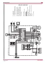
•  L’appareil doit être raccordé selon un sché-

ma de raccordement électrique comme cela 

est  indiqué  dans  ce  document  (fig.  10)  et 

comme cela est indiqué sous le couvercle de 

raccordement de la régulation automatique.

•  Le câble d’alimentation et le dispositif de pro-

tection (commutateur automatique avec une 

caractéristique C) de la centrale sont sélecti-

onnés selon le tableau 1.

•  L’appareil  doit  être  correctement  mis  à  la 

•  Устройства имеют вращающиеся части и под-

ключаются  к  электросети.  Это  может  пред-

ставлять  опасность  для  здоровья  и  жизни 

человека.  Поэтому  при  выполнении  монтаж-

ных работ необходимо соблюдать требования 

безопасности.  В  случае  возникновения  со-

мнений относительно безопасной установки и 

эксплуатации  изделия,  просим  обращаться  к 

производителю или его представителю.

•  Монтажные  работы  могут  выполнять  только 

обученные и квалифицированные работники. 

•  Убедитесь,  что  параметры  подключаемой 

электросети  соответствуют  данным,  указан-

ным на наклейке изделия на корпусе устрой-

ства. 

•  Кабель питания должен быть подобран в соот-

ветствии с мощностью устройства (Таблица 1). 

•  Устройство  должно  быть  подключено  в  со-

ответствии  с  установленной  для  него  схеме 

электроподключения,  которая  указана  в  на-

стоящем  документе  (Рис.  10),  и  как  это  изо-

бражено  под  крышкой  подключения  платы 

управления автоматики.

•  Кабель  питания  устройства  и  защитное 

устройство  (автоматический  выключатель  с 

характеристикой  С)  подбираются  по  таблице 

1.

•  Устройство должно быть заземлено.

•  Соедините  автоматику  управления  и  пульт 

управления (рис. 10, 11 и см. схему подключе-

ния пульта).

•  Units contain rotating parts and are connect-

ed to the mains. It may cause risk to people 

health and life. Therefore, it is mandatory to 

follow safety requirements when performing 

installation works. In case of any doubts re-

garding safe installation and operation of the 

unit,  please  contact  the  manufacturer  or  its 

representative.

•  Installation works shall be performed only by 

trained and qualified personnel.

•  Make  sure  that  specifications  of  the  con-

nected  mains  correspond  to  the  specifica-

tions indicated in the product label on casing 

of the unit.

•  Selected  power  supply  cable  must  corre-

spond to the power of the unit (Table 1).

•  The  unit  must  be  connected  according  the 

designed  electric  connection  diagram  as  in 

this document (Pic. 10) and as shown under 

the connection cover of the automatic control 

board.

•  The  power  supply  cable  and  protection  de-

vice (automatic switch with characteristic C) 

of the unit are selected according the Table 1. 

•  The unit must be adequately grounded. 

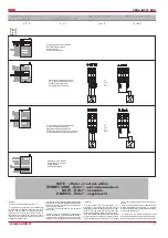
•  Connect  the  automatic  control  and  the  re-

mote controller (Pic. 10, 11 and see connec-

tion scheme of the remote controller).

•  Die Geräte verfügen über rotierende Teile und 

werden an ein Stromnetz angeschlossen. Da-

durch kann Gefahr für Leib und Leben entste-

hen.  Deshalb  sind  bei  allen  Montagearbeiten 

die Sicherheitshinweise einzuhalten. Im Zwei-

felsfall  betreffend  eine  sichere  Montage  und 

Bedienung des Produkts wenden Sie sich bitte 

an den Hersteller bzw. seinen Vertreter.

•  Die Montagearbeiten dürfen nur von geschul-

tem  und  qualifiziertem  Personal  ausgeführt 

werden.

•  Stellen  Sie  sicher,  dass  alle  Angaben  des 

Stromnetzes den Angaben des Produktaufkle-

bers auf dem Gehäuse entsprechen.

•  Das  Netzkabel  muss  der  Leistungskapazität 

des Gerätes entsprechen (Tabelle Nr. 1).

•  Das Gerät ist gemäß dem in diesem Dokument 

angegebenen Schaltplan (Abb. 10) anzuschlie-

ßen, welcher auch unter dem Deckel der Steu-

erplatine für Automatik dargestellt ist.

•  Wählen Sie das Netzkabel und die Schutzvor-

richtung (Automatikschalter mit C-Charakteris-

tik) gemäß Tabelle 1 aus.

•  Stellen Sie eine Erdung für das Gerät sicher.

•  Verbinden  Sie  die  Steuerautomatik  mit  dem 

Bedienpult (Abb. 10, 11 siehe auch Schaltplan 

des Pultes).

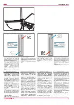
Fig. 9 

Рис. 9 

Pic. 9 

Bild 9 

поворота воздуховодов.

•  Протяните  провод,  соединяющий  автоматику 

управления  приточного  агрегата  с  пультом 

управление, и подсоедините к пульту (см. схе-

му подключения пульта).

•  Установите  пульт  управления  в  избранном 

месте.

•  Install and connect the wire between the ven-

tilation unit automatic control and the remote 

controller  (see  the  connection  diagram  for 

controller).

•  Install the remote controller in the designated 

place.

Zuluftleitung ein. Der Fühler ist möglichst weit 

vom  Gerät  bis  zur  ersten  Abzweigung  bzw. 

Biegung der Luftleitungen entfernt einzubauen.

•  Verlegen Sie das Verbindungskabel zwischen 

der Steuerautomatik des Lüftungsgerätes und 

des  Bedienpultes  und  schließen  Sie  es  am 

Bedienpult  an  (siehe  Schaltplan  des  Bedien-

pultes).

•  Montieren  Sie  das  Bedienpult  an  dem  dafür 

vorgesehenen Ort.

a

b

Entrée eau

Вода вход

Water in

Wasser in

Sortie eau

Вода выход

Water out

Wasser aus

Débit d’air entrant

Вход. воздушный поток

Inlet air flow

Einlass-Luftstrohm

Entrée eau

Вода вход

Water in

Wasser in

Sortie eau

Вода выход

Water out

Wasser aus

Débit d’air entrant

Вход. воздушный поток

Inlet air flow

Einlass-Luftstrohm

fonctionne dans un régime avec des flux de 

même  direction,  la  différence  moyenne  des 

températures diminue ce qui a une influence 

sur le rendement de la batterie (Fig. 9).

•  Installer  la  sonde  de  température  de  l’air 

soufflé dans le conduit d’air soufflé. La sonde 

est montée aussi loin que possible de la cen-

trale avant la première branche ou coude des 

conduits d’air.

•  Tirer le câble connectant la carte de contrôle 

automatique du dispositif de ventilation avec 

le  boîtier  de  commande  et  le  raccorder  au 

boitier  (cf.  schéma  de  branchement  du  boi-

tier).

•  Monter  le  boitier  de  commande  à  l’endroit 

prévu.

Содержание VEKA INT W EKO

Страница 1: ... to technical modification Производитель оставляет за собой право усовершенствования технических данных VEKA INT W EKO_P0053_AL_0003 VEKA INT W EKO CENTRALES DE TRAITEMENT D AIR ПРИТОЧНЫЕ АГРЕГАТЫ AIR HANDLING UNITS LÜFTUNGSGERÄTE Instructions de montage fr Инструкция по монтажу ru Installation instruction en Montageanleitung de ...

Страница 2: ...ntage la réparation ou la modifica tion de la centrale ne pourra être effectué qu avec le consentement écrit préalable du fabricant ou de son représentant L acheteur initial doit s assurer si la centrale convient aux conditions de l environnement choisi avant de commander et de monter la centrale Toutes les centrales sont emballées à l usine de sorte qu elles résistent aux conditions nor males de ...

Страница 3: ...au électrique autre que celui indiqué sur l éti quette du produit collée sur le boîtier de la centrale Ne jamais utiliser de câble d alimentation endommagé Ne jamais toucher avec les mains humides les câbles d alimentation connectés au ré seau électrique Ne jamais plonger les rallonges et les prises dans l eau Ne pas monter ni utiliser la centrale sur des surfaces inégales ou autres plans instable...

Страница 4: ...ater PF filter for supply air SK Air damper SP actuator SD differential pressure switch TJ air temperature sensor TV temperature sensor T1 antifrost thermostat PV ventilateur d air neuf KV aérotherme eau chaude PF filtre de l air neuf SK clapet SP servomoteur du clapet SD sonde de pression TJ sonde de température de l air TV sonde antigel T1 thermostat antigel PV вентилятор приточного воздуха KV в...

Страница 5: ...s possible from the unit to the first branch or turning of the air ducts Die Montagearbeiten dürfen nur von geschul tem und qualifiziertem Personal ausgeführt werden Das Gerät ist fest und starr zu montieren damit ein sicherer Betrieb gewährleistet ist Vor dem Anschließen an das Luftleitungssys tem sind die Anschlussöffnungen für Luftleitun gen abzudecken Schließen Sie keine Bögen in der Nähe von ...

Страница 6: ...6 www salda lt VEKA INT W EKO Fig 7 Рис 7 Pic 7 Bild 7 Fig 8 Рис 8 Pic 8 Bild 8 a a b b c c d Fig 4 Рис 4 Pic 4 Bild 4 Fig 5 Рис 5 Pic 5 Bild 5 Fig 6 Рис 6 Pic 6 Bild 6 ...

Страница 7: ...ic connection diagram as in this document Pic 10 and as shown under the connection cover of the automatic control board The power supply cable and protection de vice automatic switch with characteristic C of the unit are selected according the Table 1 The unit must be adequately grounded Connect the automatic control and the re mote controller Pic 10 11 and see connec tion scheme of the remote con...

Страница 8: ...водяного нагревателя Если установленнаятемпературанедостигнута клапан водяного нагревателя открывается до тех пор пока не достигается установленная температура Если температура приточного воздуха выше установленной клапан закрывается Клапан водяного нагревателя управляется с помощью привода 0 10VDC 24VAC Циркуляционный насос включается в зависи мости от температурной потребности а также при наружн...

Страница 9: ...9 www salda lt VEKA INT W EKO VEKA INT 1000W EKO ...

Страница 10: ...10 www salda lt VEKA INT W EKO VEKA INT 2000W EKO ...

Страница 11: ...ой воды опасно приближается к установленному пределу Тогда с целью выхода из зоны опасной controller 8 Water heater anti frost protection The protection is activated when the return water temperature becomes dangerously close to the set limit Then the water valve is forced to open and dangerous temperature range is avoided If the return water temperature reaches the set limit the assembly is stopp...

Страница 12: ...ter heater anti frost thermostat 15 C K1 Rotary pump relay K3 Air intake damper relay TR1 PCP power supply transformer F2 PCB fuse 250 mA M2 Air intake damper actuator with return spring M4 Rotary pump M5 Water cooler valve actuator 24VAC 3 position control signal M6 Water heater valve actuator 0 10VDC 24VAC PV Supply air fan motor IV Extract air fan F Automatic switch F2 Automatic switch for rota...

Страница 13: ...en bis der Ventilator zum Stillstand gekommen ist und die Heizkör per sich abgekühlt haben Beim Ausführen der Wartungsarbeiten müssen die oben genannten Arbeitssicherheitsvor schriften eingehalten werden Zusätzlich zur allgemeinen Instandhaltung und Pflege des Gerätes sind folgende Arbeiten durchzuführen Обслуживание приточного агрегата должно проводиться 3 4 раза в год Перед тем как приступить к ...

Страница 14: ... Die Rohrleitungen sind am Heizregister so anzuschließen dass sie bei Wartungs und Instandsetzungsarbeiten schnell demontiert werden können um das Heizregister aus dem Gerätegehäuse herauszunehmen Der Zu und Rücklauf der Wärmeübertrager ist so anzuschließen dass das Heizregister in entgegengesetzter Luftströmungsrichtung funktioniert Wird das Heizregister in gleicher Strömungsrichtung betrieben ve...

Страница 15: ...в замерза ния Проверить наличие теплой воды в системе отепления Температура возвратной воды не должна быть ниже 10 C Убедиться что работают узлы подачи воды и регулировки тепла циркуляционный насос привод водяного клапана см раздел Инди кация PCB Возросли шум и вибрации Почистите вентилятор как это указано в опи сании Обслуживание вентилятора Если это не помогает необходимо обратиться к поставщику...

Страница 16: ...ключение трубки Connection pipe diameter Anschluß Rohrdurchmesser DN mm Puissance totale consommée Общая потр мощность Total power consumption Total Leistungsaufnahme puissance courant мощность сила тока power current Nennleistung Nennstrom kW A Contrôle automatique intégré Авт управление установлено Automatic control integrated Integriertes Steuerungsystem Classe du filtre Класс фильтра Filter cl...

Страница 17: ...2 Jahre Garantie Wenn man ein Gerät während Transportierung beschädigt ist muss die Schaden die Trans portfirma zahlen weil wir nehmen dafür keine Verantwortung Die Geräte mit Schaden die nach Unfällen fehlerhafte Nutzung nachlässiger Aufsicht oder in Folge des Verbrauchs entstanden sind können nicht unter dieser Garantie stehen Wir werden keine Verantwortung tragen für einmalige die deswegen ents...

Страница 18: ...er replacement Filter Ersatz Tous les 3 4 mois Каждые 3 4 месяцев Every 3 4 months Alle 3 4 Monate NOTE L acheteur est tenu de remplir le Tableau de maintenance du produit ПРИМЕЧАНИЕ Покупатель обязан заполнить Таблицу обслуживание продукта NOTE The purchaser is required to fill in the Product maintenance table HINWEIS Der Käufer ist verpflichtet zu füllen Wartungstabelle des Produktes 2 Au moins ...

Отзывы: