background image

9

www.saintroch.us

732.8 *

W

39.75”

Burner

opening

Ø 5”

Drain cock

Ø 3/4"

Supply

Ø2"

Flue Collar

Ø

Return

Ø2"

24.5”

12.25”

13”

8”

26

1/4

33

1/2

12.25”

2

1/2

4. Installation of Boiler Trim Components

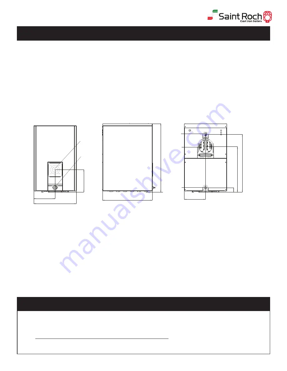
Boiler Tapping Diagram:

1.  Install limit control sensor in rear section TOP using 3/4” immersion well.  All tapings 

and joints should be sealed with piping compound.  The limit can be adjusted up to 

220

o

 F, and should be set to the desired temperature by the installer.  The differential is 

also adjustable between 5 and 30 degrees.  It should be set as close to 30 degrees as 

possible to prevent short cycling of the boiler.  Run the sensor from behind the control 

to the immersion well and fix it according to manufacturer’s instructions.  

2.  Install Pressure Relief Valve in opposite, manifold using 3” nipple and 3/4” elbow, Pipe 

must discharge to the floor. 

3.  Install 3/4” boiler drain in lower right rear tapping.

4.  Install combination pressure/temperature gauge in the manifold. The gauge must be 

tightened using a wrench and not your hand. 

5.  Place the 14” x 24” Cera-fiber blanket on the floor of the combustion chamber of the 

boiler

Trim Kit Components

:

1 – Tridicator pressure/temp gauge

1 – ¾” X 3” Nipple

1 – 30 PSI pressure relief valve

1 – ¾” Boiler drain

1 – Cera-fiber Pad for bottom of the combustion chamber

1 – ¾” Plugs

1 – ¾” 90° Elbow

1 – 

¾”  Electrowell

(Gas systems only)

1-Double acting barometric damper with manual reset spill switch 

SAFETY RELIEF VALVE

1.  The safety relief valve should be piped into one of the tapings on manifold in the 

rear of the boiler

2.  The relief valve should be installed using the hardware supplied in the trim kit 

without valving between the PRV and the boiler.

3.  Pipe the discharge for the safety relief valve with copper tube to the floor and 

make sure installation of the pipe conforms to local codes.

Содержание Optimajor OPTI GLP 6

Страница 1: ...ectric switch do not use any phone in your building Immediately call your gas supplier from a neighbor s phone Follow the gas supplier s instructions If you can not reach your gas supplier call the fire department Installation and service must be performed by a qualified licensed installer service agency or the gas supplier Danger Distributed By QHT INC 3560 LAFAYETTE ROAD BLDG 2 UNIT A PORTSMOUTH...

Страница 2: ...an specific recommendations We realize that other makes and models of such devices are available and can be used as successfully as those we specify The installing contractor is the best judge of a system s specific requirements as well as the local availability of certain makes and models of controls and accessories The preceding does not apply however to the equipment that comes with every boile...

Страница 3: ...Exhaust Venting 7 14 Blocked Flue Switch 7 1 14 Common Exhaust Venting 7 2 15 Gas Venting 7 3 15 Burner Setup 8 16 Oil Burner Setup 8 1 16 Gas Burner Setup 8 2 17 Gas Line Piping 9 18 Boiler Jacket Assembly 10 19 20 21 Baffle Installation 11 22 Wiring 12 22 Wiring Hydrostat Control 12 1 23 Oil Diagrams 12 2 24 Gas Diagrams 12 3 25 Commissioning the Boiler 13 26 Maintenance 14 26 Installer Notes 15...

Страница 4: ... proper operation See page for service record Review and explain start up and routine maintenance procedures with homeowner Fire explosion asphyxiation and electrical shock hazard Improper installation could result in death or serious injury Read this manual and understand all requirements before beginning installation Modification substitution or elimination of factory equipped supplied or specif...

Страница 5: ...lier s instructions If you can not reach your gas supplier call the fire department 7 If you don t smell gas go to the next step 8 Return the manual valve on the combination gas valve to the on position by reversing step 5 9 Turn on all electric power to the appliance 10 Set thermostat to the desired setting 11 If the burner fails to light you may press the reset button once If the appliance will ...

Страница 6: ...an then be disassembled before delivery to the jobsite by QHT and then field assembled The boiler jacket burner and controls are packed separately for shipping Note All equipment should be inspected upon delivery and any damage or shortage should be reported immediately Product Code of Sections Heating Capacity BTU HR Net Output BTU HR Length Inch Width Inch Height Inch Water Content gal Pressure ...

Страница 7: ...ne section only and slide sections together Install the four draw rods and draw the sections together evenly measure with yardstick Draw the sections together until sections make gasket to iron contact at a point around the top and bottom ports of each section DO NOT OVER TIGHTEN TIE RODS 2 Boiler Block Assembly Boiler Block Assembly 1 Rear Section 2 Intermediate Section 3 Front Section 4 5 Rear C...

Страница 8: ...ORDANCE WITH SECTION 5 3 AIR FOR COMBUSTION AND VENTILATION OF THE NATIONAL FUEL GAS CODE ANSI Z223 1 OR APPLICABLE PROVISIONS OF THE LOCAL BUILDING CODES DO NOT INSTALL THE BOILER UNTIL PROPER COMBUSTION AIR HAS BEEN ARRANGED The boiler should be installed on a level flat concrete floor or pad that is structurally sound and will support the combined weight of the boiler when filled with water Thi...

Страница 9: ...lbow Pipe must discharge to the floor 3 Install 3 4 boiler drain in lower right rear tapping 4 Install combination pressure temperature gauge in the manifold The gauge must be tightened using a wrench and not your hand 5 Place the 14 x 24 Cera fiber blanket on the floor of the combustion chamber of the boiler Trim Kit Components 1 Tridicator pressure temp gauge 1 X 3 Nipple 1 30 PSI pressure relie...

Страница 10: ...ns to impede overflow from the boiler Install the Tridicator in another port so that it can easily be read Lastly install the Manual Reset LWC in the header so that it can easily be reached for service Install manual and or automatic air venting devices at the high points in the system to eliminate trapped air The weight of all piping should be supported by suitable hangars and floor stands not by...

Страница 11: ... valve to reduce line pressure to 10 to 15 psi In the case of a gas installation the boiler should be installed such that the gas ignition system components are protected from water dripping spraying etc during appliance operation and service circulator replacement condensate trap control replacement etc If the boiler is to be used in conjunction with a chilled water system it must be piped with t...

Страница 12: ...r for combustion and ventilation is to come from outside the building Two 2 openings shall be provided with one opening commencing within 12 inches of the top and an opening commencing within 12 inches of the bottom of the enclosure These openings shall not be located closer than 3 inches from either the top or bottom of the enclosure and shall connect directly or by ducts too the outdoors The are...

Страница 13: ...s water vapor retarder with a rating of 1 perm or less with openings sealed with gaskets etc 2 Weather stripping has been added on open able windows and doors and caulking or sealants are applied to areas such as joints around windows and door frames between sole plates and floors between wall ceiling joints between wall panels at penetrations for plumbing electrical and gas lines and in other ope...

Страница 14: ...d to discharge flue gases then the power vent unit should be equipped with a postpurge control as well as delay off timing control to prevent problems with fogging and nozzle post drip Note 88 steady state efficiency is achieved when flue gas contains over 12 5 CO2 and the gross stack temp is below 350F The smoke pipe connection from the boiler to the chimney should be as short as possible with a ...

Страница 15: ...o appliance will operate continuously 5 Test for spillage at the barometric damper opening after 5 minutes of main burner operation Use the flame of a match or candle or smoke from a cigarette cigar or pipe 6 After it has been determined that each appliance remaining connected to the common venting system properly vents when tested as outlined above return the doors windows exhaust fans fireplace ...

Страница 16: ... s specs to insure proper operation 2 Installing properly sized gas piping according to BTU input required and length of gas line run 3 Making sure there is proper manifold pressure before and after the gas valve using a calibrated manometer 4 Checking draft at the breeching to insure it is adequate to overcome flue gas resistance 02 to 04 in w c 5 Setting the air band properly with well maintaine...

Страница 17: ...72 1 5 1 5 1 4 2 1 1 8 2 6 2 2 3 2 Head Setting 3 3 1 1 2 2 3 3 4 4 Air Gate 3 4 3 4 1 8 3 2 2 3 2 2 8 3 7 3 5 4 1 Note Consult burner manufacturers literature for gas manifold diagram and controls To determine how much gas is coming into the burner or to set the gas meter correctly the following formula can be used The chart to the right can be used to determine the flow rate depending upon the t...

Страница 18: ...on as the gas inlet connection to the boiler Extend the drop line with a nipple towards the floor and cap to form a sediment trap Install a shut off valve before the tee with sediment trap and a union after the tee before the combination gas valve When installing the boiler make sure a pipe compound resistant to the action of liquefied petroleum is used Check piping for leaks Always check leaks wi...

Страница 19: ...t Assembly 1 Top Casing Rail R 2 Top Casing Rail L 3 Bottom Casing Rail R 4 Bottom Casing Rail L 5 Upper Brackets 6 Lower Bracket Front 13 Upper Plate Rear 14 Block Insulation 15 Insulation Rear 18 Ext 3 Side Panel R 19 Ext 3 Side Panel L 20 Ext 3 Panel Top 7 Lower Bracket Rear 8 Common Panel R 9 Common Panel L 10 Common Panel Top 11 Insulated Front Panel 12 Lower Plate Rear 23 Ext 2 Side Panel R ...

Страница 20: ...d back tie rods as shown below STEP 2 Wrap boiler block with insulation material and strap it as shown STEP 3 Install side rails to each top and bottom brackett from front to back Attach with supplied screws MAKE SURE SHELF OF BRACKETS FACE IN TOWARDS EACH OTHER ON ALL 4 BRACKETS ...

Страница 21: ... Interlock the common top cover and proceed along with side panels and covers STEP 6 Secure two rear panels onto back of boiler casing by starting with LOWER piece first and interlocking the top piece into it Then place front door on by interlocking the bottom into the hooks on the side panels and pushing the top into position ...

Страница 22: ... in accordance to manufacturer s instructions and wiring diagrams If an external electrical source is utilized the boiler when installed must be electrically bonded to ground in accordance with the requirements of the authority having jurisdiction or in the absence of such requirements with the National Electrical Code ANSI NFPA 70 and or the Canadian Electrical Code Part 1 CSA C22 1 Electrical Co...

Страница 23: ...r Low Water Cutoff QHT has added a ground wire and providing a mechanical connection for grounding the Hydrolevel Immersion well back to the 3250 grounding lug NOTE All wiring must be done in accordance with applicable state local and national codes Use only copper conductors ...

Страница 24: ...24 12 2 Oil Burner Wiring NOTE All wiring must be done in accordance with applicable state local and national codes Use only copper conductors ...

Страница 25: ...25 www saintroch us 12 3 Gas Burner Wiring NOTE All wiring must be done in accordance with applicable state local and national codes Use only copper conductors ...

Страница 26: ...if necessary 6 Consult the burner manufacturers manual for annual maintenance of the burner 7 Once the burner has been serviced check the combustion and verify it against Section 8 on page 16 of this manual 8 Inspect the boiler and make sure it is operating normally i e temperature and pressure 9 Inspect the Pressure Relief Valve and manually set it off to ensure it is operating normally and not l...

Страница 27: ...his warranty does not apply to boilers which are subject to misuse abuse neglect alteration accident excessive temperature excessive pressure or corrosive water or atmosphere 5 Owner will be responsible for return of faulty components to Portsmouth NH freight pre paid QHT AND Saint Roch WILL NOT BE RESPONSIBLE FOR 1 Components that are part of the heating system but were not manufactured by Biasi ...

Страница 28: ...ucts shown in this guide book can be shipped next day to anywhere in the US Canada QHT has worked 35 years as a manufacturers representative for HVAC products sold to wholesale distributors in the U S and Canada Customer service and support are the key to QHT s business The staff at QHT will take care of your needs In addition to providing specialized packaging and shipping services QHT product su...

Отзывы: