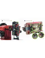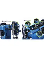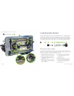
background image

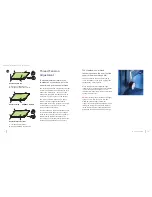
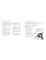
Check the Rotational Timing of the Shuttle Gib Hook

The shuttle gib hook (p. 55, 

16

) is driven by the shuttle driver (

15

). To change the rotation of the 

hook, the driver must be repositioned on the lower shaft (

14

). 

1. 

Turn the balance wheel so the gib 

hook point is at its furthest position 

counterclockwise (

42

).

2. 

Measure the distance between the gib 

hook point and the needle. The driver 

is correctly positioned when the point is 

between 1/8" and 3/16" counterclockwise 

of the needle (

A

). 

If spaced properly, the driver is set 

correctly. If not, continue on to adjust 

the driver.

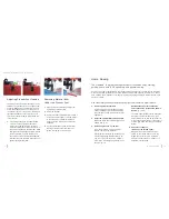
3. 

The driver is secured to the lower shaft 

with two set screws (

43

). Loosen the 

screws (

B

) and gently twist the shuttle 

driver. Keep the driver from sliding left or 

right on the shaft. If the fit is tight, carefully 

use a screwdriver as leverage.

After adjusting the rotational timing 

of the gib hook, you may need to 

adjust the rotational positioning of the 

shuttle race guide shaft or the left-right 

positioning of the shuttle gib hook. 

Check the Rotational 
Positioning of the Shuttle 
Race Guide Shaft

Before making any adjustments to the left-

right positioning of the shuttle assembly, 

check the rotational positioning of the shuttle 

race guide shaft.

1. 

Remove the needle plate (p. 49, 

18

and feed dog (p. 57, 

17 

or

 19

)

2. 

Remove the bobbin case and hook,  

re-install the retaining ring

.

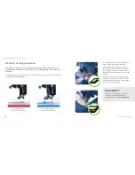
3. 

Rotate the balance wheel until the needle 

enters the shuttle (

44

). 

If positioned properly, the needle is 

centered in the “triangular” opening of 

the retaining ring cap spring from front 

to back (

C

). 

If not, you'll need to adjust the 

rotational positioning of the shuttle 

race guide shaft.

4. 

Loosen the compressible timing clamp 

screw (p. 46,


46


D

)


just a little. 

5. 

Twist the shuttle race guide shaft carefully 

without moving it left or right. If it will not 

move, loosen the compressible timing 

clamp screw a little more.

6. 

Verify that the needle is now positioned 

correctly within the retaining ring cap 

spring. 

7. 

Tighten the compressible timing clamp 

screw.

42

43

A

B

C

44

Ultrafeed

®

 Guidebook: Troubleshooting the Ultrafeed®

44

43

www.sailrite.com

Содержание Ultrafeed LS-1

Страница 1: ...ULTRAFEED LS 1 LSZ 1 GUIDEBOOK SET UP USE MAINTENANCE TROUBLESHOOTING SCHEMATICS ...

Страница 2: ... 1 Lubrication Points 22 LSZ 1 Lubrication Points 25 Troubleshooting the Ultrafeed 28 Thread Tension Doesn t Release 28 Inconsistent Stitch Tension 29 Clutch Will Not Disengage 30 Removing the Hook to Clean the Shuttle Race Guide and Free Thread Jams 30 Skipped Stitches 31 Thread Issues 33 Needle Issues 37 Bobbin Winding Issues 38 Belt Issues 39 Ultrafeed Timing 40 Hook Driver Gap 48 Schematics 49...

Страница 3: ...ot control wiring into the machine be cautious to connect the receptacles correctly to avoid electric shock WARNING Some products may be fabricated from materials which may contain chemicals known to the State of California to cause cancer birth defects or other reproductive harm THREAD SIZE GOV SIZE TEXTILE SIZE TENSILE STRENGTH NEEDLE SIZE FABRIC WEIGHT RECOMMENDED Gen Purpose N A N A N A 10 or ...

Страница 4: ... the left as you face the machine CAUTION If the needle is inserted the wrong way the machine will skip stitches and break thread To make sure your needle is inserted far enough you can look through the sighting hole 3 E near the bottom of the needle bar The top of the needle should be fully visible in the sighting hole and pushed all the way to the top A Needle bar thread guide hole B Needle groo...

Страница 5: ...GAGED Posi Pin clutch ENGAGED Thread the Bobbin On the machine 1 Thread comes off top of cone to thread stand arm A 2 Pass through thread post B 3 Wrap around bobbin tensioner C 4 Run under and up through a hole in top of bobbin D Place bobbin on post and push to the right Hold onto thread tail briefly and power machine with the clutch disengaged to wind bobbin Stop after several rotations and cut...

Страница 6: ...of bobbin tensioner C 4 Loop through ear holes D 5 Thread through upper tension shown without cover knob E Make sure lift lever F is raised up to release tension plates so thread can pass through 6 Pass through take up arm right to left G and then under end cover 7 Pass through the needle bar thread guide hole H and then down through the needle eye from left to right I A B C D E F G H I 6 Ultrafee...

Страница 7: ...foot 7 Removing Lift the spring loaded lever E and pull the bobbin case out With the lever held open the bobbin is captive in the bobbin case Release the lever and the bobbin will fall out Installing Pull and hold the spring loaded lever outward to keep the bobbin from falling out and push the case onto the axle of the gib hook The finger of the bobbin case F should point upward If the lever E is ...

Страница 8: ...the machine is threaded and the bobbin case with bobbin is installed pick up the bobbin thread as follows 1 Hold the needle thread loosely to the side 9 and rotate the balance wheel toward you until the needle moves down and then back up 2 As the needle nears its highest point pull the needle thread gently The bobbin thread should come up through the needle hole with the needle thread in the form ...

Страница 9: ...eturn to its forward position when you release it When the machine is operating at 1 4 speed or faster reverse can be engaged on the fly DO NOT rotate the balance wheel in the wrong direction Always turn it towards you from the top to avoid thread jams in the lower mechanism Turning Corners First turn the balance wheel toward you until the needle is at its lowest point Then lift the presser foot t...

Страница 10: ...ng dental floss off a spool The Ultrafeed has a thread tensioning knob on the front that the upper thread runs through 18 The upper tension knob can be turned up to five revolutions to compress a spring that squeezes two disks together When the presser foot is lifted the upper tension disks are pushed apart This releases the top thread tension so fabric can be removed from under the machine foot w...

Страница 11: ...es on heavier thread 4 Check for clockwise rotation of the thread spool When placing home sewing machine spools on the thread post be sure the thread spool is turning in a clockwise manner to ensure the post it rides on is tightened not loosened Home Sewing The Ultrafeed is a great sewing machine for those who enjoy crafting quilting home auto RV upholstery and general sewing Several of the same c...

Страница 12: ...ut the machine in straight stitch and center the needle bar Put the welting assembly under the groove so the cord is accommodated by the groove 25 The groove under the foot works to keep the bulk of the material outside the arm of the machine When sewing welting on an assembly work clockwise to ensure the bulk of the assembly stays clear of the machine i e out from under the sewing machine arm 26 ...

Страница 13: ...hine sounds like it is running roughly Marine Use Potential for Rust If the machine will be used or stored in a harsh environment lubricate the working parts of the machine with regular sewing machine oil prior to storage and before each use We also recommend using Boeshield s T 9 a paraffin based protectant to protect metal surfaces and control knobs Use even on the painted surfaces metal parts n...

Страница 14: ...Left end and back side lubrication points Underside lubrication points 29 30 Ultrafeed Guidebook Ultrafeed Maintenance 24 23 www sailrite com ...

Страница 15: ...LSZ 1 Lubrication Points Left end and back side lubrication points Top side lubrication points Right end lubrication points 31 32 33 Ultrafeed Guidebook Ultrafeed Maintenance 26 25 www sailrite com ...

Страница 16: ...ion assembly 35 might have pulled away from the machine To fix the tension you will need to move the core closer to the machine 1 Remove the left end cover p 49 13 of the machine exposing the internal parts 2 Using an Allen wrench loosen the set screw located directly behind the tension assembly p 49 12 3 With the presser foot up push the upper tension assembly in until you feel the first signs of...

Страница 17: ... and sloppy near the tension assembly under operation check your take up spring p 28 35 H If the wire hook has broken off you ll need to replace the take up spring To do this you ll need to disassemble the upper tension assembly Keep track of how the parts are removed as they will be replaced in the same manner p 28 35 1 Pull the cover knob A straight off wiggle a bit if needed 2 Unscrew and remov...

Страница 18: ...d 2 Not Enough Foot Pressure Heavy closely woven materials like sailcloth and canvas can make the withdrawal of the needle from the fabric difficult If the presser foot is being lifted as the needle comes out of the cloth the loop that the needle forms will be too small Increase the downward pressure on the presser foot by tightening the pressure regulating thumb screw p 12 13 3 Burred Gib Hook or...

Страница 19: ...rst few inches of sewing and then clears up Eliminate this formation by trapping the thread tails from the needle and the bobbin as you start to sew Thread Issues Thread is shredding balling or breaking There are a number of causes for breaking thread Start with Step 1 and stop as soon as the problem is resolved 1 Incorrectly Installed or Damaged Needle Make sure your needle is installed correctly...

Страница 20: ...djustments to fine tune your Ultrafeed Stitches are skipped in straight or zigzag operation 1 Mount the thread spool horizontally Every time the thread pulls off the top of the cone a twist is put in the thread Eventually these twists add up and an erratic loop forms at the hook When the hook misses catching the thread loop the machine skips a stitch Make a roller out of a dowel rod or an old coat...

Страница 21: ...self is loose 1 Make sure the spring pin is properly inserted 2 If slipping still occurs remove the Posi Pin nut p 61 2 pull out the spring pin 1 3 5 and slide the balance wheel off the bushing 3 Use a 2 5 mm Allen wrench to tighten the two set screws 34 that fasten the bushing to the machine s upper shaft then reinstall the balance wheel and check for proper operation Bobbin Winding Issues The bo...

Страница 22: ...loosening the shaft the pulley may be moved to re tension the belt Tighten the shaft to complete the adjustment Ultrafeed Timing The timing of your machine is determined by the relationship of the needle to the gib hook The gib hook picks up the upper thread at the needle and carries it down around the bottom of the bobbin case where the upper thread loop is pulled tight by the take up arm above t...

Страница 23: ...the needle bar to the bottom of its stroke all the way down Unlock the needle bar from the drive collar by loosening the set screw located either in the front or the side of the pillow block C If the screw is in the side of the pillow block it can be accessed through a hole in the machine casting D Use a 1 8 flat blade screwdriver to loosen Do not use the screwdriver that comes with the machine it...

Страница 24: ... shaft or the left right positioning of the shuttle gib hook Check the Rotational Positioning of the Shuttle Race Guide Shaft Before making any adjustments to the left right positioning of the shuttle assembly check the rotational positioning of the shuttle race guide shaft 1 Remove the needle plate p 49 18 and feed dog p 57 17 or 19 2 Remove the bobbin case and hook re install the retaining ring ...

Страница 25: ... machine to straight stitch 2 Make a mark on the cast iron bearing surface next to the large oil hole 46 B in the shuttle race guide shaft C If the shaft should accidentally rotate realign the mark with the oil hole 3 Loosen slightly the compressible timing clamp screw D on the compressible timing clamp that drives the entire assembly back and forth with the zigzag movement of the needle Increment...

Страница 26: ...in the center shaft To move the hook to the right 7 Loosen the two screws in the right collar E and move it to the left on its shaft and move the shuttle assembly D to the right 8 Move the assembly to position the hook as close to the needle as possible without deflecting p 45 45 9 Holding the correct position of the shaft move the right collar E as far right as possible without touching the frame...

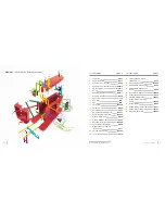
Страница 27: ...er Tension Assembly includes 28 8511 23 Bobbin Winder W030Z 24 Screw 100576 or A036 25 Thread Guard Screw 103253 26 Top Plate Set Screw E072 27 Bobbin Winder Ring 120181 28 Thread Take Up Spring included in 22 5332 29 Tension Release Pin W184 2 30 Shuttle Race Slide Spring A049 31 Shuttle Race Slide Spring Screw A050 32 Straight Stitch Position Guide W001Z 33 Take Up Arm Guard 102626 34 Set Screw ...

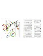
Страница 28: ...rew 103263 17 Needle Plate 5mm W032 18 Needle Plate Screw A052 19 Shuttle Race Slide 120346 20 Three Hole Thread Guide W029 21 Upper Tension Assembly includes 24 8511 22 Thread Guard Screw 103253 23 Top Plate Set Screw E072 24 Thread Take Up Spring included in 21 5332 25 Tension Release Pin W184 2 26 Shuttle Race Slide Spring A049 27 Shuttle Race Slide Spring Screw A050 28 Take Up Arm Guard 102626...

Страница 29: ... 30 Presser Bar A035 1 31 Presser Bar Lower Bushing B028 32 Presser Bar Bracket W039 33 Presser Bar Feed Actuator Pivot Screw 103257 34 Tension Release Lever Drag Link W043 35 Tension Release Lever Drag Link Set Pin D020 36 Tension Release Lever W045 37 Tension Release Lever Set Screw B046 38 Zigzag Drive Gear Cam W016Z 39 Presser Bar Actuator Cam W065 40 Helical Gear W000Z 41 Needle Displacement ...

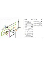
Страница 30: ...amp Screw B153 13 Shuttle Race Guide Shaft B170 14 Lower Shaft B172 15 Shuttle Driver W172 16 Shuttle Gib Hook 9601 17 Bobbin 123100 18 Bobbin Case Assembly 1232 19 Screw B139 2 20 Zigzag Shuttle Drive Assembly W002Z 21 Retaining Ring Cap Spring 1603 22 Retaining Ring Clip Set 123011 23 Retaining Ring Clip Spring 103273 24 Retaining Ring Clip Screw 103274 25 Retaining Ring for Ultrafeed 102241 26 ...

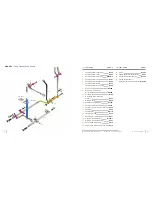
Страница 31: ...aft Crank A071B 14 Feed Rock Shaft A071A 15 Feed Bar Center Screw Nut A076 16 Feed Bar A075 17 Feed Dog W011Z 18 Feed Dog Screw A078 19 Feed Dog W011 20 Driving Crank Guide Nut W046 1 21 Driving Crank Guide Screw A061 22 Feed Lifting Rock Shaft A072 23 Feed Lifting Rock Shaft Crank A073 24 Screw B139 2 25 Feed Regulator Wavy Washer A067 26 Forked Rod Support Spring B103U 27 Forked Rod Support Spri...

Страница 32: ...r W014 24 Screw C097 25 Presser Bar Feed Rod W036 26 Presser Bar Actuator Spacer W024 1 27 Bearing Bracket Bushing W021 28 Lift Crank Rod Bearing Plate W023 29 Rocker End Set Ring W052 30 Presser Bar Actuator Rocker W033 31 Presser Bar Actuator Feed Rocker W034 32 Crank Rod Rocker W035 33 Crank Rod W053 34 Set Screw 103640 35 Screw A036 or 100576 36 Presser Bar Actuator Rocker Screw 103272 37 Guid...

Страница 33: ...6 Motor Bracket Lock Washer LT 2M 3 17 Motor Bracket Bolt LT 2M 2 18 Belt Cover W050BL 19 Belt Cover Screw 100576 or A036 20 Motor Base W049Z 21 Motor Base W049 22 Motor Base Screw W049 1 23 Motor Bracket Washer 103266 24 Motor Bracket Nut 103268 25 Motor 102630 110V 102731 220 240V 26 Motor Pulley W062 1 27 Set Screw W052 1 28 Bracket 102712 29 Top Bracket Mount Screw 103260 30 Bottom Bracket Mou...

Страница 34: ...A 20 5 mm Dia x 10 8 mm H NEEDLE SIZE RANGE 10 22 THREAD RANGE Home Sizes to V 92 HEAD WEIGHT 35 lbs All parts and labor are fully guaranteed for 2 years by Sailrite We are proud to provide you with everything you need to successfully maintain and repair your Ultrafeed Should you choose to return your machine for repairs you will be responsible for delivery both ways PLEASE NOTE Damage due to impr...

Страница 35: ...103280 1 Guidebook for Sailrite Ultrafeed LS 1 LSZ 1 Qty 1 Version V3 1 Ultrafeed PATENTED TECHNOLOGY Patents 6499415 7438009 Sailrite com Equipping you to sew at home on the water Copyright 2016 ...

Отзывы: