background image

ICOP PRO HD HVR USER GUIDE

28

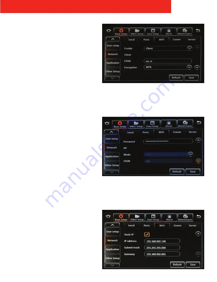
WiFi

Tap in the 

Enable

 field and select 

Client

 to enable the 

internal WiFi module. Enter the following information:

• 

ESSID

• 

Encryption

• 

Password: 

Enter an alphanumeric password  

NOTE:

 This password will also be used when adding 

the ICOP PRO HD vehicle to the DVMS PRO software

• 

Static IP:

 If the checkbox is checked, device will be 

considered as static device

• 

IP address:

 Enter a Static IP address for the internal 

WiFi module

• 

Subnet mask:

 Enter a static subnet mask for the 

internal WiFi module

• 

Gateway:

 Enter a static network gateway for the 

internal WiFi module

Then tap the 

Save 

button.

Содержание ICOP PRO HD HVR

Страница 1: ...ICOP PRO HD HVR USER GUIDE...

Страница 2: ...ot limited to the implied warranties of merchantability and fitness for a particular purpose Safety Vision shall not be liable for errors contained herein or for incidental or consequential damages in...

Страница 3: ...tus LCD Front Panel Buttons 8 ICOP PRO HD Touch Screen Monitor Installation 9 Components 10 ICOP PRO HD Windshield Camera Components 11 ICPMICKIT Microphone Cradle Installation 12 Components 13 ICOP P...

Страница 4: ...p General 41 Advanced 43 Alarm Panel Alarm 47 HDD SD Video 52 Motion 54 Cover 55 Advanced 57 Maintenance Config 59 Category File Data 60 Data Export Upgrade 61 Storage 61 Reset 61 Officer Login 62 App...

Страница 5: ...ngs ICP Wireless Mic Rugged remote microphones record sound and start and stop recordings while an officer is away from the vehicle HD Windshield Camera The HD Windshield camera faces out of the winds...

Страница 6: ...ption Sensor Description 1 INPUT SENSOR 1 6 INPUT SENSOR 6 2 INPUT SENSOR 2 7 INPUT NOT USED 3 INPUT SENSOR 3 8 INPUT NOT USED 4 INPUT SENSOR 4 1 OUTPUT NOT USED 5 INPUT SENSOR 5 2 OUTPUT NOT USED Tab...

Страница 7: ...d secure the mount with four appropriate screws Flat Mount 1 Place the supplied L brackets on each side of the HVR oriented up or down depending on the intended installation 2 Secure the L brackets to...

Страница 8: ...udes both the primary and mirror SD cards in a secure container 4 Lock The Lock secures the storage media devices and turns the ICOP PRO HD HVR on and off 5 Removable Hard Drive The solid state drive...

Страница 9: ...drive 1 Insert the key into the lock and turn it clockwise Unlocking the lock powers the HVR off 2 Pull storage canister straight out 3 When finished replace the storage media back into recorder 4 Tur...

Страница 10: ...SD card not installed Main SD card OK Main SD card not formatted Mirror SD Status Mirror SD card error Mirror SD card full Mirror SD card not installed Mirror SD card OK Mirror SD card not format Reco...

Страница 11: ...he RAM mount to the back of the touch screen monitor with the two provided Phillips head screws horizontally in either the high or low position SV LCD Mount Slide the touch screen monitor onto the LCD...

Страница 12: ...the Play Pause and Stop buttons to play pause or stop video playback respectively The Stop button also stops a recording 7 Menu Button Press the Menu button to access the video playback and configura...

Страница 13: ...to fully zoomed in position Press and Hold Increase zoom to desired position 4 Auto Zoom Zoom to a preset value for 10 seconds then return to original position Single Press Perform Auto Zoom Preset A...

Страница 14: ...e vehicle with six supplied Phillips head screws or other appropriate fasteners Note Do not install the cradle in an area that could interfere with the safe operation of the vehicle 3 Ensure the Power...

Страница 15: ...displays green 3 Press the Record button once more to conclude recording The In USE status LED turns off 4 Replace the microphone in the cradle when not in use or when the battery is low 4 Status LED...

Страница 16: ...following features REC Recording Search Search for and playback previously recorded video System View the recorder s system details and current status Log Search Search the recorder s log files to vi...

Страница 17: ...ormal green video recorded not as a result of a configured alarm continuous recording etc Select a day on the calendar then tap the Next button to advance to the channel selection screen Channels Sele...

Страница 18: ...ht side of the screen to return to the video search results Export Tapping the Export button on the results screen begins the export process Selected video can be downloaded to a USB flash drive 1 Ins...

Страница 19: ...e played back using the DVMS PRO software AVI data video is exported in avi format which can be played by most commonly available media players 9 Tap OK The video clip is exported automatically If the...

Страница 20: ...avigate between different menus Version Info The Version Info menu provides information on the firmware version of the recorder in addition to other information Device Name Name of recorder DVMS PRO I...

Страница 21: ...address of the internal WiFi module External WIFI Status Displays the status of a connected external WiFi device ESSID ESSID of a connected external WiFi device IP address IP address of a connected ex...

Страница 22: ...d in volts the recorder is currently receiving Device temperature Displays the internal temperature of the recorder in both Celsius and Fahrenheit HDD heater status Displays if the internal HDD heater...

Страница 23: ...ging configurations etc Locked log Log of when video was locked Alarm log Log of different types of alarms After selecting this option the Alarm Type field appears Alarm Type Field options All All ala...

Страница 24: ...aded to a USB flash drive 1 Insert a USB flash drive into the USB port on the front panel of the recorder 2 Select any of the alarm log results you want to export video for by tapping in any of the bo...

Страница 25: ...menu configures basic recorder settings such as the date time start up and shutdown parameters etc Basic Info Device Info DVMS PRO ID Unique numeric ID assigned to the recorder for identification in t...

Страница 26: ...elect this option to automatically synchronize the date and time to a DVMS PRO server when the recorder connects NTP sync Select this option to automatically synchronize the date and time to an offici...

Страница 27: ...he Timer ON OFF mode Monitor mode Select Automatic Power Up to turn the touch screen monitor on automatically with the recorder Select Auto Standby to leave the touch screen monitor in standby mode mu...

Страница 28: ...User Setup Idle Time Select the number of minutes after no activity that the touch screen monitor automatically exits a Menu and displays the live camera views Select Never to keep this function disa...

Страница 29: ...order Subnet mask Enter a static subnet mask for the recorder Gateway Enter a static network gateway for the recorder Auto get DNS Select this option to allow the recorder to receive DNS information a...

Страница 30: ...TE This password will also be used when adding the ICOP PRO HD vehicle to the DVMS PRO software Static IP If the checkbox is checked device will be considered as static device IP address Enter a Stati...

Страница 31: ...ble box option and enter the following information Protocol type Select N9M Enable network Select Local Register server IP Enter the DVMS PRO server IP address Register server port Default port is 555...

Страница 32: ...ots to be uploaded to the FTP See Snap Setting under Data Setup for more information Enter the following information about the FTP server Server Port User name Password Then tap the Save button Downlo...

Страница 33: ...Preview Window Select this option to display live camera views on the touch screen monitor upon system startup System Status Select this option to display the system status screen on the touch screen...

Страница 34: ...ontrast COL Color SAT Saturation Then tap the Save button Select a channel in the Copy to field and tap Copy to automatically copy the same settings to additional channels Margins Tap the Setup button...

Страница 35: ...the Auto Loop Enable option at the bottom of the screen Tap the Add Screen button or tap an existing screen s Setup icon to display the Edit Screen and enter the following Mode Select 1x1 one channel...

Страница 36: ...its default position Then tap the Save button to return to the Live OSD menu screen Then tap the Save button WMIC WIRELESS MIC MUTE ENABLE Select this option to allow users to mute audio from the wire...

Страница 37: ...ion to prevent the primary storage device from overwriting Lock duration Enter the time between 1 and 31 days that recorded files are locked during which time the recorder is prevented from recording...

Страница 38: ...ing in a lower resolution higher resolution recording when an alarm is activated Normal Frame Rate Select between 1 and 30 frames per second Normal Quality bit rate Select between 1 and 8 1 being the...

Страница 39: ...larms only None does not record dual stream Sub Record provides stream for Live View in DVMS PRO see Sub Record Setup below Channels Select which channels are recorded in the second stream Then tap th...

Страница 40: ...Vehicle Plate GPS Channel Name Vehicle Num Then tap the Save button Where the metadata appears overlaid relative to its position on the screen can be adjusted Tap the Setup button to display the posit...

Страница 41: ...een appears Enter the following for each network Channel Protocol Type IP address Port Username Password 41H series IP cameras leave the Username and Password fields blank Gen 3 60 32000X Exterior and...

Страница 42: ...ch attached PTZ camera configure the following Channel Enable Select this option to enable PTZ functions Operate Select Serial N9N or ONVIF Protocol Type Select Pelco D or Pelco P Addr Enter the numbe...

Страница 43: ...the selected sensor that will appear on the on screen display when the sensor is active People counting Under development Then tap the Save button Serial Port The Serial Port tab configures which devi...

Страница 44: ...ICOP PRO HD HVR USER GUIDE 42 GPS Navigation mode Under development Mileage The Mileage tab tracks the total miles the recorder has been installed in the vehicle...

Страница 45: ...nu to configure snapshots to be taken during set intervals Select the Time snap option at the bottom of the screen Then tap the Add button to add a time period Enter a Start time and End time for the...

Страница 46: ...he best Upload type Select FTP uploads the snapshots to the FTP client Snap numbers Select the number of snapshots between 1 and 3 taken at each interval Interval Select the interval that snapshots ar...

Страница 47: ...specific to this type of alarm see Linkage Setup below Then tap the Save button Trigger Setup Tap the Setup button under the Trigger field to display the setup screen to configure the parameters spec...

Страница 48: ...ion to lock the video during this alarm to prevent the recorder from overwriting it Linkage screen Select the screen type that appears on the monitor while the alarm is active either None Single or Qu...

Страница 49: ...ee Trigger Setup below Linkage Tap the Setup button to configure the recording monitor display and additional options specific to this type of alarm see Linkage Setup below Then tap the Save button Tr...

Страница 50: ...ion to lock the video during this alarm to prevent the recorder from overwriting it Linkage screen Select the screen type that appears on the monitor while the alarm is active either None Single or Qu...

Страница 51: ...DISPLAY ONLY Sensor input does not start or stop recording only displays text on OSD and is stored in metadata if DVR is recording at the time Trigger Tap the Setup button to configure the parameters...

Страница 52: ...elect the channels that are recorded for the duration of this alarm Post recording Enter the amount of time between 1 and 30 minutes the alarm records video after it is triggered Lock Select this opti...

Страница 53: ...configure the parameters specific to this type of alarm see Trigger Setup below Then tap the Save button Trigger Setup Tap the Setup button under the Trigger field to display the setup screen to conf...

Страница 54: ...rameters specific to this type of alarm see Trigger Setup below Linkage Tap the Setup button to configure the recording monitor display and additional options specific to this type of alarm see Linkag...

Страница 55: ...ption to lock the video during this alarm to prevent the recorder from overwriting it Linkage screen Select the screen type that appears on the monitor while the alarm is active either None Single or...

Страница 56: ...SER GUIDE 54 Motion Select the Motion option to trigger alarms when motion is detected in the selected camera channels During configuration select the portion of the field of view in which motion will...

Страница 57: ...lay and additional options specific to this type of alarm see Linkage Setup below Then tap the Save button Trigger Setup Tap the Setup button under the Trigger field to display the setup screen to con...

Страница 58: ...ion to lock the video during this alarm to prevent the recorder from overwriting it Linkage screen Select the screen type that appears on the monitor while the alarm is active either None Single or Qu...

Страница 59: ...on to configure the recording monitor display and additional options specific to this type of alarm see Linkage Setup below Calibrate Tap the Calibrate button while the recorder is still to reset the...

Страница 60: ...larm is active either None Single or Quad tap the Setup button to select the channels that appear in each screen section and the Duration between 1 and 300 seconds that it appears on the monitor PB al...

Страница 61: ...ry of the flash drive To upload a configuration file to a recorder insert a USB flash drive with a configuration file present on the root directory into the USB port on the front panel of the recorder...

Страница 62: ...t Export time to request only data in a specific time range Enter a Start Time and End Time then under File Type select from the following GPS data file Vehicle info file ACC info file Can info file u...

Страница 63: ...irmware CP4 Upgrade to upgrade the touch screen monitor s firmware or IPC upgrade to upgrade any connected IP cameras The firmware upgrade process begins automatically Make sure recorder maintains con...

Страница 64: ...icer Login menu allows you to log in multiple officers simultaneously if more than one officer is assigned to the vehicle Tap the Login icon to display the log in window Tap in the User name and Passw...

Страница 65: ...card canister holds 2 SD cards Recording Modes Alarm only Sensor light bar weapon rack etc trigger speed acceleration video loss temperature background alarm continuous Pre event Recording Configurab...

Страница 66: ...ICOP PRO HD HVR USER GUIDE 64 Appendix B Dimensions ICOP PRO HD HVR Power Control Monitor...

Страница 67: ...ated in a commercial environment This equipment generates uses and can radiate radio frequency energy and if not installed and used in accordance with the instruction manual may cause harmful interfer...

Страница 68: ...opyright 2018 Safety Vision LLC All Rights Reserved CORPORATE HEADQUARTERS 6100 W Sam Houston Pkwy N Houston TX 77041 5113 Main 713 896 6600 Toll Free 800 880 8855 Fax 713 896 6640 www safetyvision co...

Отзывы: