


48 SERIES IP CAMERA
5
1 - Power Input:
Input power, connect to DC 12V power, and please be sure
to power the device according to the instruction of device label.
2 - Alarm I/O:
Input and output wires for alarm. Refer to “Alarm I/O” table for
details.
3 - Network port:
Network data transmission and Power over Ethernet (PoE)
power supply.
4 - Audio Out:
Output audio signal to the speakers and other devices.
5 - Audio In:
Input audio signal, receive analog audio signal from other
devices.
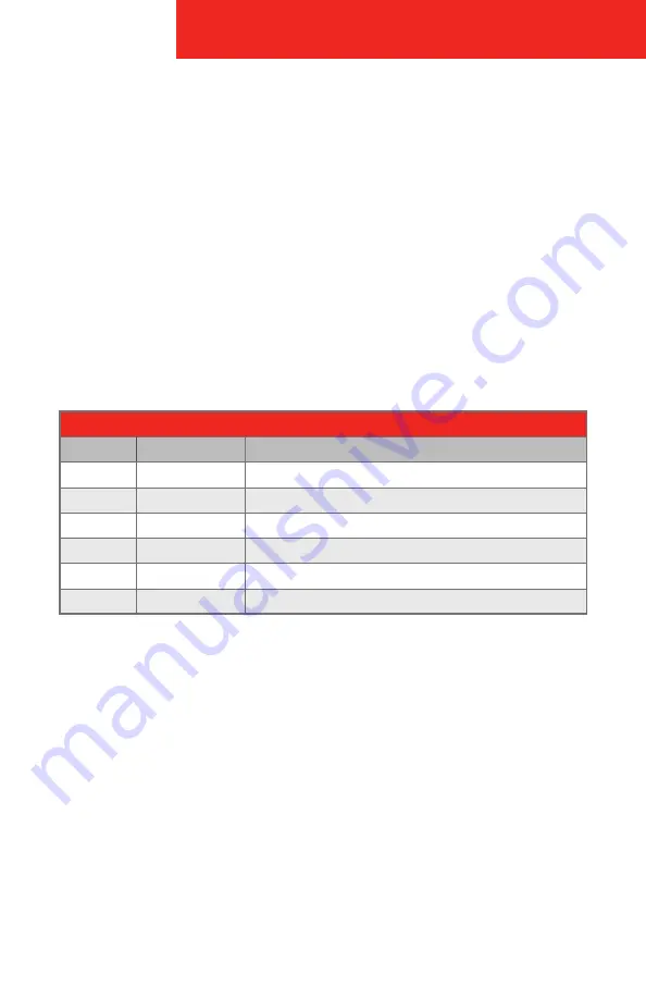
ALARM I/O CONNECTIONS
COLOR
PORT NAME
DESCRIPTION
Blue
ALARM_IN1
Alarm input port 1, receive on-off signal from external alarm source.
Brown
ALARM_OUT1
Alarm output port 1, output alarm signal to alarm device.
Green
ALARM_OUT_GND1 GND 1
White
ALARM_IN2
Alarm input port 2, receive on-off signal from external alarm source.
Red
ALARM_OUT2
Alarm output port 2, output alarm signal to alarm device.
Black
ALARM_OUT_GND2 GND 2
Содержание 48 Series
Страница 1: ...48 SERIES IP CAMERA USER GUIDE...
Страница 20: ...48 SERIES IP CAMERA 18 Appendix B Dimensions...
Страница 22: ...48 SERIES IP CAMERA 20 Memo...
Страница 23: ...48 SERIES IP CAMERA 21 Memo...


