background image

© Safe Fleet | 2020 | All rights reserved | Part #: 700-1213 R1

DH4C Installation Guide

p. 40

DH4C Advanced Configuration

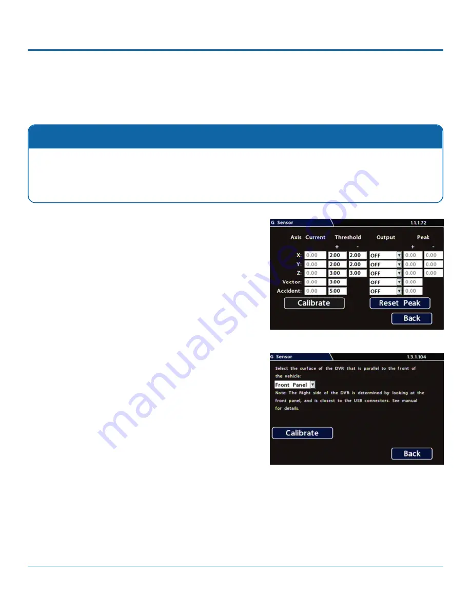
G-Sensor

Configuring G-Sensor Options

i.  Ensure all DVR surfaces are parallel to the front of the 

vehicle and perpendicular to the floor.

ii.  Click 

Calibrate

.

3. 

In the G Sensor calibration menu, from the drop down field, 

select the DVR surface that is parallel to the front of the 

vehicle.

4. 

Click Calibrate for the G Sensor to set the X/Y/Z axis planes, 

based on the mounting surface selection. When the process 

is done, a "Calibration Complete" message appears.

5. 

If required, adjust G Sensor settings. For details, see Menu 

Options, below.

6. 

Click Back to save settings, then click Back again to return to 

the Configuration menu.

 Calibration 

The G-Sensor must be calibrated when initially installed or if the unit is relocated, and the procedure must be per-

formed on the vehicle (i.e. not by connecting to the DVR from a remote location).

G-Sensor settings can be adjusted to fit specific requirements. Note that if thresholds are set too low and alarms are 

enabled, many alarms may be generated. Details are provided below.

To configure G-Sensor settings:

1.  Select 

Alarm/Signal 

 G-Sensor

 to open the tab.

2. 

If this is a new system installation, or the DVR has been 

relocated, perform the following Calibration procedure:

Содержание DH4C

Страница 1: ... Safe Fleet 2020 All rights reserved Part 700 1213 R1 Installation Guide DH4C 4 Channel DVR ...

Страница 2: ... Safe Fleet 2020 All rights reserved Part 700 1213 R1 this page left intentionally blank ...

Страница 3: ... screen Keyboards 14 Health Check 15 DH4C Administration 16 Accessing the On screen Display 16 Working with Video 19 DH4C Basic Configuration 22 Setting up the DVR 22 Time and Date 24 Title and Display 25 Camera Settings 27 Configuring Signals 28 Alarm Settings 30 Copying DVR Configuration 32 DH4C Advanced Configuration 34 Configuring Recording Settings 34 Network Settings 36 Advanced Network Sett...

Страница 4: ... built in GPS WIFI antenna built in WIFI Smart Reach WIFI bridge Smart Reach cellular router Portable video monitor Required Tools Equipment The DVR system must be installed by a professional installer A professional installer has the experience and equipment to install and configure the components to run properly Check that you have all the system components and inspect the units for any scratche...

Страница 5: ...dem 4 POE LAN Input independently powered Laptop 4 POE LAN Input Portable Video Monitor 5 VIDEO OUT Optional Accessories 1 Vehicle speed and location tracking require the GPS antenna 2 Built in WIFI requires an external antenna 3 The RGY button is optional and requires the RGY extension harness 4 Only one of the Smart Reach Lite the Smart Reach Cellular modem or a laptop can connect to the POE LAN...

Страница 6: ...surface that is subject to constant vibration ORIENTATION Install the DVR horizontally vertically or upside down CLEARANCE Allow sufficient clearance of at least 6 inches in front of the DVR and 2 inches to each side for removal of the security front cover and easy access to the USB ports Allow sufficient clearance behind the DVR for camera cables mounting cables Ethernet cables and power cables M...

Страница 7: ...or down until it clicks 4 Insert the key into the SD card lock and rotate a quarter turn to lock the drive 5 Select an appropriate mounting location and orientation For more information see DH4C Installation Requirements 6 Fasten the DVR to the mounting surface with the four self drilling screws 7 Connect the necessary cables and components For more information find the DH4C Quick Installation Gui...

Страница 8: ... and the optional RGY Button To install the Adapter Harness 1 Connect the 2x6 Microfit from the harness to the DVR rear panel SIGNALS socket 2 Connect the 5 signal input wires 3 Connect the Adapter s 1x5 Microfit to the RGY button extension harness optional For more information see the System Diagram on page 5 To DVR SIGNALS socket 2 x 6 To Signal inputs 5 wires To RGY Button extn harness 1 x 5 Un...

Страница 9: ...te 6 Once the update is finished the DVR automatically restarts 7 Remove the USB memory device Completing Upgrade After restarting the DVR may take up to 3 minutes to load and complete the upgrade Wait until the DVR finishes loading Firmware Updates Firmware controls how DVR features operate including the Playback and Configuration menu displays Safe Fleet Technical Support may direct you to insta...

Страница 10: ... video monitor into DVR and power up the DVR from the vehicle ignition Configure the DVR to required specifications locally using the mouse and monitor or remotely with a Web browser via WiFi or Ethernet using a PC For more information see Basic Configuration on page 21 Confirm the ERR SD and PWR status indicators on the DVR front panel work properly Confirm that all cameras and audio sources oper...

Страница 11: ...er powers on the DVR for five minutes if held for more than 5 seconds powers down the DVR if held for more than 5 seconds in temporary power mode or in shutdown sequence with ignition off 6 USB Port supports USB devices used to copy video and audio information export video clips update DVR firmware import export configuration data and archives 7 Mouse Port connection for USB mouse 8 Status Lights ...

Страница 12: ...na 3 CAM 1 to CAM 4 input connectors 6 pin for four cameras 4 GPS SMA input connector for GPS antenna 5 CTRL control connector for Safe Fleet equipment 6 SIGNALS connector for signal harness with an optional adapter for the RGY Button 7 POWER input for power harness POE LAN Port is 12 volt In addition to the data transmitted the POE Power Over Ethernet LAN port supplies 12 volts to power accessori...

Страница 13: ... green Color Recorder Status Examples Green Recording normal no video loss from any camera no problems with recording operation Routine operations including recording warming up booting shutting down Yellow Recording video loss recording but experiencing video loss from one or more cameras Video loss on any or all channels 1 Red Not recording system unable to record due to an abnormal condition No...

Страница 14: ...r video management applications Commander or Depot Manager tagged video can be automatically downloaded and made available to reviewers when your vehicle returns to the depot Commander provides these capabilities using a cloud based architecture designed to simplify total deployment management and upkeep while Depot Manager provides the same capabilities in a non cloud or local deployment For more...

Страница 15: ...play Health Check information 1 Select Title Display 2 Health Check ITEM DESCRIPTION GPS Connectivity indicator green when a GPS location fix is achieved otherwise red POE LAN Connectivity indicator green when a cable is connected from the DVR s front POE LAN port to an operational network device otherwise red WiFi Connectivity indicator green when connected to a WiFi network access point otherwis...

Страница 16: ...ing we recommend Evidence Manager The software is supported on a Windows based computer For more information see the Evidence Manager User Guide on the Safe Fleet Community To use the On screen Display 1 Connect a portable video monitor to VIDEO OUT on the DVR front panel 2 Plug a USB mouse in a USB socket on the front of the DVR 3 Power up the DVR The DVR splash screen appears briefly The system ...

Страница 17: ...MERA_TITLE Appears in the top left corner of each viewing section in the example FRONT MID HD SIZE Formatted size of the primary recording media SD card in gigabytes GB OFF indicates the media is not present HD USED Percentage of primary media storage space used by recorded video OFF indicates the media is not present At 100 the message displayed depends on the Repeat Record settings in the Record...

Страница 18: ...E DVR temperature in degrees Fahrenheit or Celsius TIME AND DATE Current recorded time and date GPS COORDINATES If GPS is connected the actual coordinates latitude longitude and heading appear If GPS is connected but the satellite signal is not being received zeros are displayed AC ALARM COUNT Number of alarms triggered Resets to 0 when DVR is restarted IG Highlights when vehicle ignition is on ...

Страница 19: ...play menus 1 Connect a portable monitor and USB mouse and power up the DVR For more information see DH4C Administration Accessing the On Screen Display 2 Right click anywhere in the OSD view to access the Main Menu 3 Click Playback 4 In the center of the Playback View click the Show Hide icon The Playback Toolbar appears 5 Click the icons to browse video and archive clips Multi camera View Playbac...

Страница 20: ...yback F Fast Forward Fast forwards playback With playback paused each click advances the video by one frame G Individual Camera Multi view Displays a single camera feed 1 2 3 or 4 or multi view all 4 cameras H Audio Cycles through Audio for channel 1 2 3 4 5 or 6 I Metadata Text Overlay Turns on text overlay temperature system voltage GPS data if recorded speed date and time For more information s...

Страница 21: ...en Keyboards 3 If desired use the Search Only pull down and corresponding sub menus to specify Alarms Signals or System Events to search 4 Click Search If Search Only is set to Time Playback starts from the specified time and date if the video exists on the SD card If you select Alarms Signals or System Events The DVR retrieves a list of recorded video segments containing the specified event type ...

Страница 22: ...deo search playback and archiving features Logging in to the DVR with a Web Browser requires the proper network configuration to establish a connection and a browser extension to display the user interface For more information find the vMax Web User Guide on the Safe Fleet Community Plug an RJ 45 Ethernet cable into the back panel LAN port or connect remotely over a network if you have Smart Reach...

Страница 23: ...uts Alarms and Signals Speed If the DVR is used in Canadian fleets select the KPH speed units Alarms and Signals DH4C external G Sensor If a G Sensor is installed Calibrate Network If an external Smart Reach WiFi bridge is used set addresses as instructed by an IT administrator Use the IP address shown to communicate with the DVR over the network with vMax Web Network Advanced If a Smart Reach Cel...

Страница 24: ...reen Keyboards 3 Click Back to save the settings and return to the Configuration menu MENU ITEM DESCRIPTION Daylight Saving Leave ON and at default dates unless in an area that does not use daylight savings e g Arizona Saskatchewan Click DST Settings and ensure the Start End dates and times apply to your location ON Time Zone Select your local time zone UTC 05 Eastern Standard Time Time Format Cho...

Страница 25: ...s below MENU ITEM DESCRIPTION VALUE DEFAULT Main Title Enter the bus number MAIN_TITLE Titles Display Display hide Main Title and Camera Titles ON OFF Time Date Display Display hide time and date ON OFF Record Status Display Display hide DVR recording status LIVE showing camera feeds RECORD storing video V LOSS video loss ON OFF System Data Display Display hide DVR system metadata HDD Size primary...

Страница 26: ...nput voltage Temperature Ambient temperature inside the DVR F Fahrenheit C Celsius Signals When a signal activates the Label is displayed GPS Coordinates Latitude longitude and elevation If GPS is connected but satellite signals are not being received zeros appear Alarm Count AC The current number 1 9 of triggered Alarms The value resets to 0 when the DVR restarts For more information see DH4C Con...

Страница 27: ...p the cameras For details see Menu Options below 3 Click Back to save Camera settings then click Back again to return to the Configuration menu ITEM DESCRIPTION VALUE DEFAULT Title For each camera enter a name that describes the view it is recording For example Front Step Mid Rear Stop Arm For instructions on how to enter text with the mouse see DH4C Operation Using On screen Keyboards Camera titl...

Страница 28: ...camera channels ON OFF Apply CH1 to All Click to apply settings selected for Channel 1 to all cameras n a Camera Advanced Click to access the Camera Advanced tab and adjust settings for each camera with CoC Control over Coax n a Configuring Signals The DVR supports 10 independent signals The first five are dedicated input wire signal harness connections LT left turn signal STP stop BRK brake WRN w...

Страница 29: ...play associated labels during video playback Signals 6 through 10 can be user defined n a Label You can edit the on screen display text label maximum 3 characters to describe each signal as desired For instructions on using the mouse to enter data see DH4C Operation Using On screen Keyboards Labels 1 through 5 LT STP BRK WRN RT Labels 6 through 10 S06 S07 S08 S09 S10 Level Control how the signal s...

Страница 30: ...larms By default Alarm 1 is connected to the optional RGY button installed in the vehicle for use by the operator for more information see Flagging Video for Review Alarms 2 4 can be triggered automatically by vehicle speed a G sensor threshold GPS fencing or when a Signal is activated To Configure Alarms 1 Select Alarm Signal Alarms to open the tab 2 Configure Alarm settings as required For detai...

Страница 31: ... choose N C Normally Closed if the circuit rests at 12 VDC and drops to 0 when active N O N C FPS For each channel the recording speed in FPS Frames Per Second used when the alarm is triggered If the DVR normally records at a mid range or low FPS to conserve storage space set a higher FPS value to increase video quality for a short duration to record an alarm event OFF 1 5 7 10 15 20 30 FPS Qualit...

Страница 32: ...nal assignments system preferences and networking details For more information see DH4C Configuration Setting up the DVR This procedure requires physical access to the DVR you want to copy settings from a portable video monitor a USB mouse and a USB storage device formatted by a Windows computer using the FAT 3 Right click anywhere in the OSD view to access the Main Menu 4 Select Configuration Sys...

Страница 33: ... whether or not to overwrite DVR network settings No keeps existing DVR network settings Yes overwrites DVR network settings with configuration from the file To copy configuration to a DVR from a USB storage device 1 Power up the DVR using the vehicle ignition 2 Connect the portable video monitor and USB mouse 3 Insert a USB storage device containing a configuration file into the USB port on the D...

Страница 34: ... the oldest video when it becomes full the HD Used metadata item displays Repeating for more information see DH4C Configuration Title Display Menu When set to OFF the DVR stops recording when storage is full HD Used displays 100 ON OFF Record On Delay Time Leave at default to let the voltage settle after the vehicle starts up to prevent voltage drops affecting the DVR Enables a time delay after th...

Страница 35: ...for full detailed event information and the other Record2 at lower resolution for fast downloading or real time viewing over a low bandwidth network such as a cellular link In the event of an emergency if the system is configured with Smart Reach cellular hardware and a cellular plan Record2 allows quick access to video online Use the Record2 setting to specify a lower per second recording frame r...

Страница 36: ...art Reach Mobile wireless bridge or for more information To configure Network Settings 1 Select Network to open the tab 2 Configure settings as required For details see Menu Options below 3 Click Back to save settings and return to the Configuration menu Note Configuring WIFI If the DVR s built in WIFI is used see Built in WIFI Settings on page 39 If the DVR is attached to an external WIFI bridge ...

Страница 37: ...ss uniquely identifies a host or computer on the LAN which connects the subnet to other networks Enter the LAN Gateway as determined by a qualified network expert 169 254 1 1 DNS Server Uses an IP address composed of four octets separated by decimals 0 0 0 0 MAC Address MAC Media Access Control is the DVR s unique hardware number Fixed HTTP Port Typically leave the HTTP Port set to 80 unless other...

Страница 38: ...er network s LAN range as determined by a qualified network expert Note There must be a value in this field If not used enter a dummy IP address such as 10 10 0 0 0 0 0 0 LAN Subnet Mask Set the LAN subnet mask used for the LAN Gateway Destination range as determined by a qualified network expert Use a value between 0 and 32 16 iVML IP Address Enter the iVML IP Address as determined by a qualified...

Страница 39: ...gain twice to return to the Configuration menu ITEM DESCRIPTION VALUE DEFAULT SSID Enter the WIFI network name as defined by the network administrator n a Password Enter the WIFI network password as defined by the network administrator n a Setting Type Choose Static IP or DHCP to enable built in WIFI Contact the network administrator for the required Setting Type Static IP uses a permanent address...

Страница 40: ...age appears 5 If required adjust G Sensor settings For details see Menu Options below 6 Click Back to save settings then click Back again to return to the Configuration menu Calibration The G Sensor must be calibrated when initially installed or if the unit is relocated and the procedure must be per formed on the vehicle i e not by connecting to the DVR from a remote location G Sensor settings can...

Страница 41: ... of X and Y axes to capture driver behavior incidents Accident combination of X and Y axes higher threshold settings to capture vehicle accidents n a Current The current live values measured by the G Sensor display only n a Threshold Set from 0G to 6 0G This value configures the threshold level Any value beyond the threshold triggers the output as configured in the Output field X 2 00 Y 2 00 Z 3 0...

Страница 42: ...SCRIPTION VALUE DEFAULT Speed Units Choose MPH in the US or Km h in Canada The speed display units the GPS signal is converted to display speed in the selected units MPH Miles per hour KM h Kilometers per hour KTS Knots Speed Limit Enter a speed limit to trigger notifications If an Excessive Speed Action is selected this value triggers a notification if exceeded by vehicle speed 0 Excessive Speed ...

Страница 43: ...uration menu ITEM DESCRIPTION VALUE DEFAULT Fencing Alarm ALM settings trigger the selected Alarm when the vehicle crosses the fencing boundary as defined by the selected coordinate style OFF ALM1 ALM4 Coordinate Style Circle sets the area for GPS fencing by identifying the center point and radius This option only displays Circle center and Radius data entry fields Rectangle Sets the area for GPS ...

Страница 44: ...figuring User Levels To configure User Levels 1 Select Network User Levels to open the tab 2 The default Admin user cannot be changed Add other users with access levels as required Enter user names passwords and assign levels For details see Menu Options below 3 Click Back to save changes then click Back again to return to the Configuration menu Password Control Users logging on to the DVR should ...

Страница 45: ...r Levels or reset the DVR to default configuration Viewer only live camera feeds no viewing or archiving recorded video Administrator for User 1 Playback for other Users Configure Viewer Menu Options System Settings Configuring System Settings To configure System Settings 1 Select System to open the tab 2 Adjust system settings as required For details see Menu Options below 3 Click Back to save ch...

Страница 46: ...information see DH4C Operation DVR Status Button RGY Illum RGY Button Language Select a language for the DVR On screen Display and vMax Web UI English Spanish French Dutch German Menu Options Monitor Settings Configuring Monitor Settings Monitor Settings control camera feeds sent to the Video Out RCA jack on the DVR front panel To configure Monitor Settings 1 Select Title Display Monitor Settings ...

Страница 47: ...a by Channel number all connected cameras UP or to show each active camera feed in sequence Sequence applies only to the Timer option described below Channel 01 UP Sequence Switch On Set the trigger type that will activate the camera feed selected in the Switch To setting and cause it to display in the monitor output Then from the pull down menu below select a specific Alarm Signal or Timer settin...

Страница 48: ...s Seon Warranty pdf Appendix Contact Safe Fleet Technical Support Phone 1 844 899 7366 Email PTsupport safefleet net Returns If your DVR is to be returned please contact Technical Support and provide the model and or serial number of your unit Ask for a Return Merchandise Authorization RMA number An RMA number allows the Service Technicians to better track your product when it comes in for service...

Отзывы: