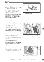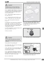
9.4.2 Insert the new bellows (9) into the holding
sleeve (T07) of the tool combination (C). Ensure
that the folds of the bellows are inside the tool
(see Fig. arrow B).
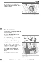
9.4.3 Insert the holding sleeve (T07) of the tool
combination (C) with the bellows (9) into the bore
and hand tighten the screw (T10) (see Fig.).
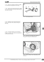
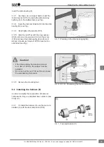
9.4.4 Then insert the bellows (9) with a maximum
torque of 8 Nm (see Fig.). Remove the tool combi-
nation C.
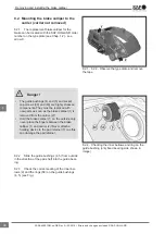
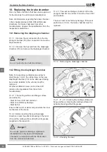
9.4.5 Ensure the correct seating of the bel-
lows (9). Perform a tension test (see Fig. 9.4.5).
9.4.6 Smear the brass bushing (7) and slide
bearing (6) with white grease (supplied in the repair
kit).
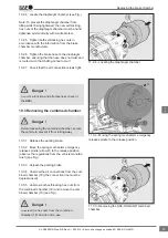
9.4.7 Install the guide bushings (4, 5) (see Fig.).
9.2.4 - 9.4.3 - Inserting the new bellows with
the tool combination (C) into the bore and hand
tightening T10
9.4.4 - Inserting with max. torque of 8 Nm
9.4.5 - Ensuring the correct seating of the bellows
9.4.7 - Inserting the guide bushing
Repairing the brake calliper bearing
44
en
XL-SA40001RM-en-DE Rev A • 02.2016 • Errors and changes excluded © SAF-HOLLAND


