


14
0171-761-EN
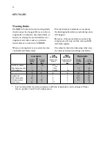
Low and high alarm limit settings
The following table indicates the permitted
limit settings for low and high alarms.
(White fields).
Low alarm
Low
High
High alarm
Limit for
setting
Factory
setting
(Add to low
(Subtract from
high alarm)
Factory
setting
Limit
for setting
Bar
Bar
Bar
Bar
Bar
warning
warning
alarm)
Suction pressure
Discharge pressure
Diff. pressure
Superheat
Discharge temp.
Oil temperature
Brine temp.
-1
3,5
5
°
C
Sat
--
--
7
-1
0
0
-20
0
-45
-1
0
2
0
20
0
1 Bar
0,5 Bar
1
5
5
2
1
0,5
5
5
5
--
18
1,5
80
120
60
--
25
25
120
145
105
15
°
C
°
C
°
C
°
C
°
C
°
C
**
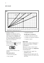
** If you compensate for cable length (see Configuration, Fig. 1), the compensation
value will reduce this max. value.
Note:
·
The high limit - the LED in the
column
for suction pressure and brine tempera-
ture are
set points
for regulation and
not
alarm limits. Please refer to the section
entitled
Automatic operation
.
·
If the low alarm limit for superheat is set
at 0, alarms and warnings will not be gi-
ven when the superheat reaches 0
°
C and
the compressor will
not
stop.
A value of 0 may be relevant on an R717
pump circulation plant, where the super-
heat can in practice be 0. This can hap-
pen even if the suction gas to the com-
pressor is dry.
Important:
If possible, the superheat alarm should be
allowed to function, as it protects the com-
pressor from liquid hammer during normal
operation.
However, it doesn’t prevent liquid from flo-
wing with the suction gas to the compressor
in the event of a plant error. This will, of
course, cause liquid hammer in the com-
pressor and obviously the fault must be
found and rectified.
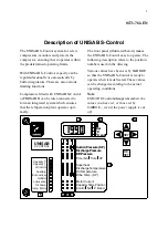
Содержание UNISAB S-Control
Страница 1: ......


