8
Sabine Smart Spectrum
®
Wireless
© 2011 Sabine
, Inc.
3. QuICk SETuPS
3.1. Receiver & Transmitter Quick Setup
Please read
Section Four Transmitter Operation
and
Section Five Receiver Operation
for a complete understanding of how to set up
your Sabine Smart Spectrum True Mobility
TM
System.
Quick Setups
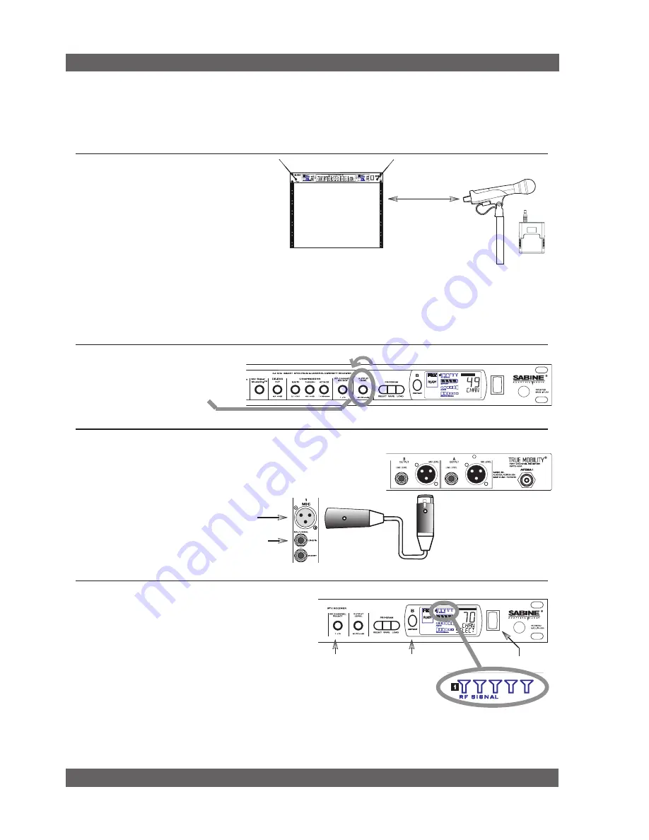
Turn the OUTPUT LEVEL of the
receiver and mixer gain to the mini-
mum settings.
2
Connect the output (¼-inch or XLR jack) of your receiver to the
mic or line input of your mixer or amplifier (the receiver output
gain can be adjusted to match the mixer input).
3
Mixer Balanced Input
(XLR)
Mixer Unbalanced Input
(TRS)
1. Turn on the receiver.
2. Tap the
Channel Select/Contrast button
to edit
a receiver channel. (Not necessary on 1-channel
SW71-R & SW61-R receivers).
3. Turn the
RF Channel Selector
knob
to the de-
sired channel.
NOTE:
Dual channel receivers will not allow you to select
the same RF channel for both channels.
4
Power Switch
RF Channel
Selector
Channel Select/
Contrast button
(selects receiver
channel to edit)
Transmitter range is 100
meters line-of-sight
Be sure that all transmitters are off.
Position receiver so that the antennas are within visual range of the intended
transmitter locations. Transmitter range is about 100 meters, but structural objects in the transmission path can reduce
that range. For best results, maintain a line-of-sight path between receiver antennas and transmitters (see Section
12). Use the
TNC Rear-to-Front kit
(SWA700) included with the receiver to move antennas to front if necessary.
See Appendix B for more information on multiple-system connection.
Use Sabine’s SWASS-EXT
Extension Antenna Kit when
line-of-sight path is not possible
from receiver location.
1
NOTE:
Front panel RF Signal display will only register Sabine transmitters. It will not show RF interference. Use the RF
Scan function in the software to scan for potential RF interference.
Selecting RF Channels:
It is best
to keep
the system’s channels close together at
the low or high end of the spectrum
, i.e.
channels 1, 2, 3, 4, 5 or channels 65, 66, 67,
68 (31, 32, 33, 34 on SWM6000 series). If
there is another 915 MHz or 2.4 GHz source
in the room, grouping the channels reduces
the chances of an overlap. Do not start by
spreading your channels throughout the full
channel range of the system – you are more
likely to encounter interference this way.
Содержание SWM6000
Страница 2: ......


