THERMASGARD
®
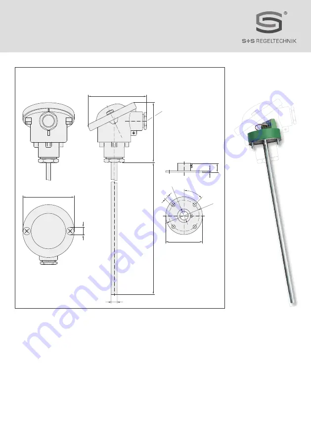
RGTM 1
D G F r
Maßzeichnung
RGTM1
Dimensional drawing
Plan coté Габаритный чертеж
Messeinsatz
Measuring insert Insert de mesure
Измерительная вставка
~ 80
~
73
M20 x1.5
ø8
ø50
ø41
ø8.3
ø5
45°
12
2
NL
ø70
ø
10
Страница 1: ...ltung und aktivem Ausgang G Operating Instructions Mounting Installation Duct flue gas temperature measuring transducers including mounting flange calibrateable with multi range switching and active o...
Страница 2: ...THERMASGARD RGTM1 D G F r Ma zeichnung RGTM1 Dimensional drawing Plan cot RGTM1 Messeinsatz Measuring insert Insert de mesure 80 73 M20 x1 5 8 50 41 8 3 5 45 12 2 NL 70 10...
Страница 3: ...Die F hler sind werkseitig abgeglichen Eine Feinabgleich durch den Anwender ist m glich Spanne Nullpunkt sind einstellbar TECHNISCHE DATEN Spannungsversorgung 24 V AC DC 10 bei Ausgang 0 10 V 15 35 V...
Страница 4: ...b VERSORGUNGSSPANNUNG Als Verpolungsschutz der Betriebsspannung ist bei dieser Ger tevariante eine Einweggleichrichtung bzw Verpolungschutzdiode integriert Diese interne Einweggleichrichtung erlaubt a...
Страница 5: ...onen St e sind zu vermeiden 0 5 g Achtung Ber cksichtigen Sie in jedem Fall die mechanischen und thermischen Belastungsgrenzen der Schutzrohre nach DIN 43763 bzw nach speziellen S S Standards Hinweise...
Страница 6: ...ent These sensors are factory calibrated Adjustment fine adjustment by the user is possible range and zero point are adjustable TECHNICAL DATA Power supply 24 V AC DC 10 for output 0 10 V 15 35 V DC f...
Страница 7: ...ltage V DC Admissible range Connecting scheme Parallel operation Connecting scheme Individual operation SUPPLY VOLTAGE For operating voltage reverse polarity protection a one way rectifier or reverse...
Страница 8: ...vibrations shocks are to be avoided 0 5 g Attention In any case please observe the mechanical and thermal load limits of protective tubes according to DIN 43763 respectively according to specific S S...
Страница 9: ...igur es en usine L ajustage fin l talonnage fin peut tre fait par l utilisateur la fin d chelle et le point z ro sont r glables CARACT RISTIQUES TECHNIQUES Tension d alimentation 24 V ca cc 10 pour so...
Страница 10: ...e terrain peut endommager cet appareil Veillez donc au raccordement correct des fils Circuitry Circuitry 0 10V 0V GND 0 10V 0V GND Power supply AC 24V 0V DC 15 36V GND Circuitry 0 10V 0V GND V Power s...
Страница 11: ...montage dimensions des tubes viter les oscillations vibrations chocs 0 5 g Attention Il faut imp rativement tenir compte des limites de solli citation m caniques et thermiques des tubes de protection...
Страница 12: ...0089 800 RGTM 1 U EL IP54 U RGTM1 U 200MM Pt1000 0 10 200 1101 3121 0049 800 RGTM1 U 250MM Pt1000 0 10 250 1101 3121 0059 800 RGTM1 U 300MM Pt1000 0 10 300 1101 3121 0069 800 RGTM1 U 400MM Pt1000 0 1...
Страница 13: ...6 4 2 0 0 1 5 0 5 2 5 3 5 4 5 1 0 2 0 3 0 4 0 Ua B 800 700 600 500 400 300 250 50 200 10 15 20 25 30 35 36 40 Load resistance diagram Working resistance Ohm Operating voltage V DC Admissible range 0...
Страница 14: ...00 125 150 175 200 225 250 275 300 325 350 375 400 0 10 15 5 20 25 30 35 40 50 75 100 125 150 175 200 225 250 275 300 325 350 375 400 0 8 10 12 14 4 6 16 20 18 22 24 26 28 30 2 TH ms xx TH VA xx TH VA...
Страница 15: ...Mounting diagram Sch ma de montage Copyright by S S Regeltechnik GmbH Nachdruck auch auszugsweise nur mit Genehmigung von S S Regeltechnik GmbH gestattet Reprints in part or in total are only permitt...
Страница 16: ...C 100 C O N OFF O N O N 0 C 200 C OFF OFF O N O N 0 C 300 C O N O N OFF O N 0 C 400 C OFF O N OFF O N 0 C 500 C O N OFF OFF O N 0 C 600 C OFF OFF OFF O N 1 2 3 4 1 2 3 4 5 6 ON 230V AC 24V DC Pt1000 N...