


4
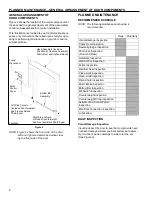
PLANNED MAINTENANCE—QUARTERLY INSPECTION
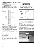
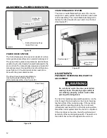
Set Screws
Receiver
Module
Designation
Alignment Light
(Yellow)
Bolts
A8500079
Drive Sprockets
A2500259
Figure 5
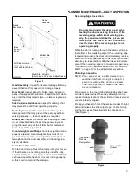
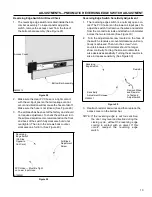
HEAD ASSEMBLY
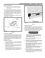
Figure 6
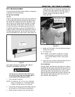
QUARTERLY INSPECTION
The disconnect must be in the OFF posi-
tion and properly locked and tagged before
performing the following procedure.
Hardware Inspection
Make sure all nuts, bolts, set screws, and anchors are
tight throughout the door. Example: motor mounting
bolts, wall mounting hardware, floor anchors, sprocket
set screws, etc. (See Figure 6 through Figure 10)
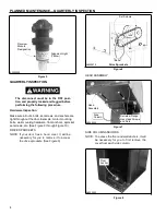
DRIVE SPROCKETS
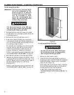
Head
Assembly
Side
Column
A8500085
Serrated-Flange
Hex Head Screws
and Nuts
Figure 7
NOTE: If your door has a hood cover, it will be
necessary for you to remove it to access
the drive sprockets. (See Figure 6)
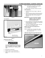
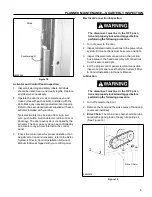
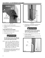
SIDE COLUMN ANCHORS
NOTE: To access the floor and wall anchors, it will
be necessary for you to first remove the
cover from each side column.
Floor
Anchor
A8500083
Figure 8


