background image

VJ1000

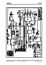
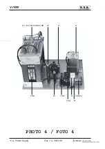
4 / 4 - Power Supply

Technical Appendix

Rev. 1.0 - 26/02/01

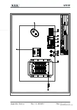
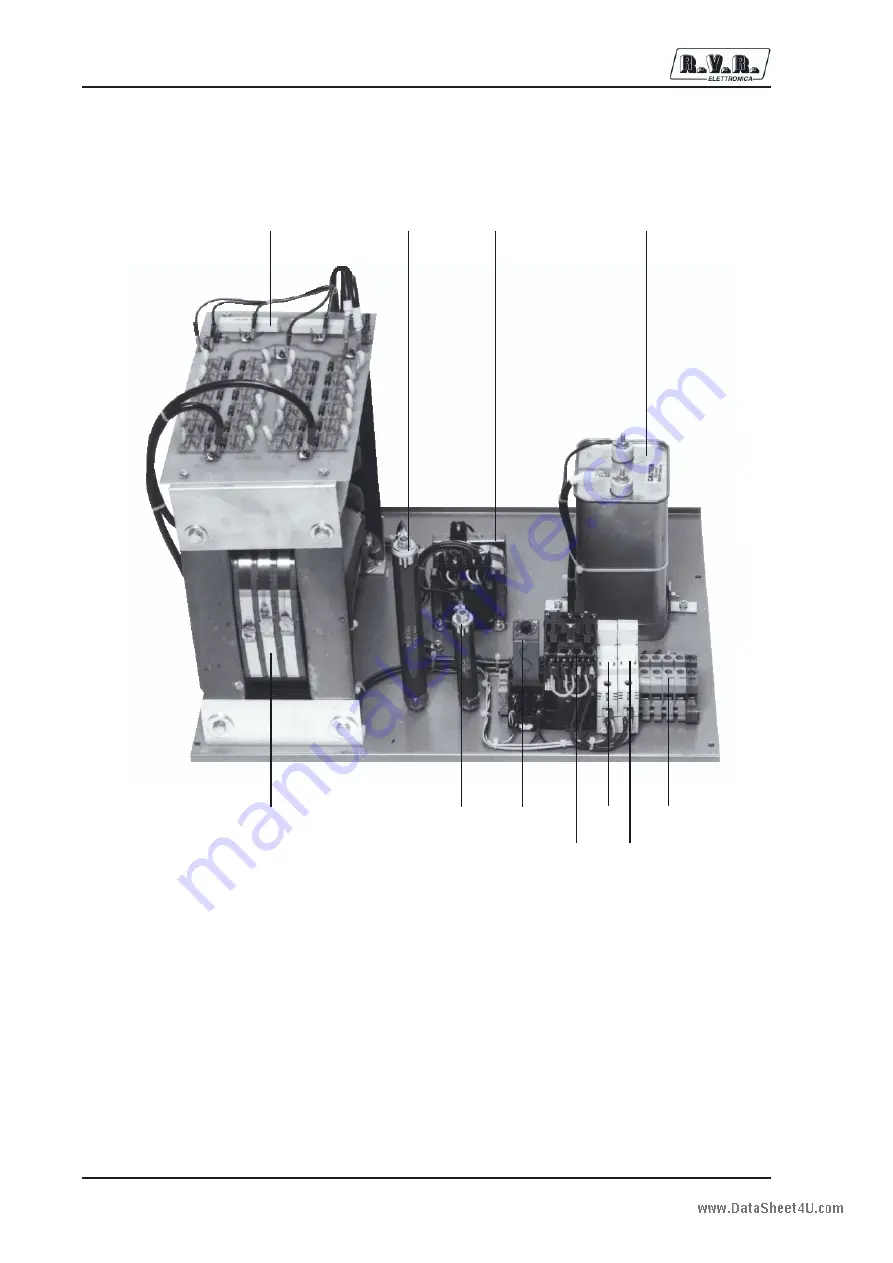
                            TEL1     F2

                H.T. RECTIFIER BOARD       R1

           T1

                C1

             TRF1

           R2       TIM1

        F1     MORS1

PHOTO 4 / FOTO 4

www.DataSheet4U.com

Содержание VJ1000

Страница 1: ...Prodotto da Italia VJ1000 User Manual www DataSheet4U com ...

Страница 2: ...6011104 Email info rvr it Web www rvr it All rights reserved Printed and bound in Italy No part of this manual may be reproduced memorized or transmitted in any form or by any means eletronic or mechanic including photocopying recording or by any information storage and retrieval system whithout the permission of the copyright owner www DataSheet4U com ...

Страница 3: ...ntroduction 10 5 2 Power Supply 10 5 3 Protection Card 10 5 4 Tube 10 6 Installation Procedure 24 6 1 Introduction 24 6 2 Unpacking 24 6 3 Fitting the Tube 24 6 4 Connection and Setup Procedures 24 6 5 Fault Finding during the Setup Procedure 26 7 Maintenance Procedure 28 7 1 Safety Procedures 28 7 2 Routine Maintenance 28 7 3 Replacement of Components 28 7 4 Replacement of the Tube 29 7 5 Changin...

Страница 4: ...3 0 26 02 01 9 1 Telemetry Connector 37 10 Telemetry Card Option 38 10 1 Calibration of the Voltages on the Telemetry connector 38 10 2 Wiring Connections details 38 10 3 General Verifications 39 Appendix 40 www DataSheet4U com ...

Страница 5: ... responsibility for injury or damage resulting from improper procedures or practices by untrained unqualified personnel in the handling of this unit Please observe all local codes and fire protection standards in the operations of this unit WARNING always disconnect power before opening covers or removing any part of this unit Use appropriate grounding procedures to short out capacitors and high v...

Страница 6: ...R within five 5 days from its receipt To claim your rights under this warranty a Contact the dealer or distributor where you purchased the unit Describe the problem and ask if he has an easy solution Dealers and Distributors are supplied with all the information about problems that may occur and usually they can repair the unit quicker than what the manufacturer could do Very often installing erro...

Страница 7: ... the problems found and a copy of your original invoice establishing the starting date of the warranty Replacement and warranty parts may be order from the following address Be sure to include the equipment model and serial number as well as part description and part number R V R Elettronica SpA Via del Fonditore 2 2c 40138 BOLOGNA ITALY Tel 39 051 6010506 www DataSheet4U com ...

Страница 8: ...serve for breathing if not breathing begin artificial breathing Figure 2 tilt head pinch nostrils make airtight seal four quick full breaths Remember mouth to mouth resuscitation must be commenced as soon as possible Figure 1 Figure 2 Check carotid pulse Figura 3 if pulse is absent begin artificial circulation Figura 4 depressing sternum 1 1 2 TO 2 Figure 5 Figura 3 Figura 4 Figura 5 APPROX 80 SEC...

Страница 9: ... medical help will not be available within an hour and the victim is conscious and not vomiting give him a weak solution of salt and soda 1 level teaspoonful of salt and 1 2 level teaspoonful of baking soda to each quart of water neither hot or cold Allow victim to sip slowly about 4 ounces half a glass over a period of 15 minutes Discontinue fluid if vomiting occurs Do not give alcohol 3 2 2 Less...

Страница 10: ...and The VJ1000 is available in single phase version 4 3 Controls and Indicators Two analog meters are present on the front panel one measures direct power output and reflected power output 1 Fig 1 the other measures plate and grid currents 3 Fig 1 The output power meter has only one scale 1KW f s both for the measurement of the direct power output and for reflected power output The meter for the m...

Страница 11: ...e the unit if the condition has returned to normal unless a panel is still open or the cooling system lacks sufficient pressure In this event the procedure is repeated four times after which the unit will remain disactivated for 15 minutes If after 15 minutes the condition is still present four more switch on attempts are made after which the unit is shut down indefinately Should during these cycl...

Страница 12: ... on request Output Power 850 1000 W RF Output Impedance 50 Ohm Output Connector LC connector 7 8 o 7 16 RF Input Impedance 50 Ohm Input Connector N type connector RF Input Power 18 W typical max 25 W Tube EIMAC 3CX800 A7 Cooling System Forced ventilation Harmonic and Spurious Meets or exceeds FCC and CCIR Signal Soppression regulations www DataSheet4U com ...

Страница 13: ...NSIONAL AND ENVIRONMENTAL SPECIFICATIONS Rack Dimensions 540mm 21 26 W 540mm 21 26 D 698 3mm 27 49 H Panel Dimensions 483mm 19 W 443mm 17 44 H Weight 60 Kg Operating Temperature Range da 10 a 45 C Maximum Humidity max 90 senza condensa www DataSheet4U com ...

Страница 14: ...uch as relays and the protection system This power supply is designed to work at single phase voltages 5 3 Protection Card This card is mounted in a metal box and fixed to the right hand side of the RF chamber s chassis 6 Photo 2 This sub unit has three alarm inputs which carry the signal to a comparator which compares them to a pre defined threshold Should one of these inputs exceed the alarm thr...

Страница 15: ... Max Frequency 350 MHz Cooling System Forced Ventilation Filament Voltage 13 5 V Filament Current 1 5 A Capacitance with Grounded Grid Ingresso 26 0 pF Uscita 6 1 pF Capacità passante 0 05 pF Base Large Wafer Elevenar 11 pin with rings JEDEC No E11 81 Amplificator Factor 200 Recommended Air System Socket SK2210 Reccomended Air Chimney SK1906 www DataSheet4U com ...

Страница 16: ... USER MANUAL Rev 3 0 26 02 01 Maximum Anode and Seal 250 C Core Temperature Maximum Lenght 64 01 mm 2 52 inch Maximum Diameter 64 26 mm 2 53 inch Weight 0 326 Kg 11 5oz Operational Position Any www DataSheet4U com ...

Страница 17: ...d of range at 87 5 MHZ OFF signifies end of range 7 PLATE Anode tuning swich 8 LED 108 LED to indicate that tuning has reached end of range at 108 MHZ OFF signifies end of range 9 LOAD Load matching switch 10 V S W R Indicator shwing excess V S W R 11 PRESS Indicator showing insufficent fan pressure 12 I G Alarm indicator for excess grid current 13 H T Indicator showing high voltage active 14 ON P...

Страница 18: ...VJ1000 14 40 USER MANUAL Rev 3 0 26 02 01 FIG 1 www DataSheet4U com ...

Страница 19: ...and filament transformer 2 Anode supply filter capacitator 3 High voltage rectifier board 4 Anode supply transformer 5 High voltage resistor 6 High voltage resistor 7 Anode delay timer 8 Solenoid switch 9 Line fuse holders 10 Line power connector 11 Exciter supply 12 Earth www DataSheet4U com ...

Страница 20: ...VJ1000 16 40 USER MANUAL Rev 3 0 26 02 01 FIG 2 www DataSheet4U com ...

Страница 21: ...trol motor 3 Output connector to antenna 4 End of tuning range switch 87 5MHz 5 Directional coupler for output power measurement 6 Line 7 Tube 8 End of tuning range switch 108Mhz 9 Low pass filter 10 Teflon C capacitator 11 High voltage input connector 12 Load matching capacitator CV 13 Micro Switch www DataSheet4U com ...

Страница 22: ...VJ1000 18 40 USER MANUAL Rev 3 0 26 02 01 PHOTO 1 3 1 2 5 7 11 9 4 6 8 12 10 www DataSheet4U com ...

Страница 23: ...40 USER MANUAL Rev 3 0 26 02 01 R F BLOCK S VIE DESCRIPTION PHOTO 2 1 Plate tuning control motor 2 Cooling air outlet 3 Air flow switch 4 Input connector to exciter 5 Air blower 6 Alarms card www DataSheet4U com ...

Страница 24: ...VJ1000 20 40 USER MANUAL Rev 3 0 26 02 01 PHOTO 2 1 2 3 4 5 6 www DataSheet4U com ...

Страница 25: ... R F BLOCK S VIEW 2 DESCRIPTION PHOTO 3 1 End of tuning range switch 87 5 Mhz 2 Input Matching Board 3 Load tuning control motor 4 End of tuning control motor 108 Mhz 5 Multipolar circolar connector 6 Grid Plate meter board www DataSheet4U com ...

Страница 26: ...VJ1000 22 40 USER MANUAL Rev 3 0 26 02 01 PHOTO 3 6 1 2 5 4 3 w w w D a t a S h e e t 4 U c o m ...

Страница 27: ... 01 TABLE D TYPICAL VALUES OF THE OPERATING PARAMETERS Power Voltage Nominal Tension 5 MAX COS FI better than 0 9 Output Power 1 KW approx Input Power 18 20 W Anode Current 0 45 A Grid Current or 20 mA Input SWR 2 W MAX www DataSheet4U com ...

Страница 28: ...ssing lightly and first rechecking the correct alignment of the pins 4 Check that the tube is fully home in its socket verifying the correct fit of the grid ring 5 Shut the high voltage panel and re fit all the screws 6 4 Connection and Setup Procedures To connect the unit follow the following instructions 1 Remove the rear panel 2 Connect a cable of suitable dimensions the unit can draw up to 15A...

Страница 29: ...he TUNING switch activate the tuning motors so that both green leds next to the PLATE control light up Holding the TUNING switch down use the PLATE or control the unit is factory set to a frequency of 98 MHz to tune the anode circuit indicates an increase in frequency and a reduction in frequency If one of the leds switches off this indicates that the end of the frequency range has been reached an...

Страница 30: ... operates at high voltages which are dangerous and potentially lethal For this reason the unit should only be operated with all its panels securely in place The unit must be connected to a good earth The unit should be operated in a well ventilated environment the hot air expelled by the unit will rapidly raise the temperature of a poorly ventilated environment with potentially damaging consequenc...

Страница 31: ...T EQUIPMENT INSTRUMENT TYPE SUGGESTED MODEL TECH SPECIFICATIONS Non Inductive Bird 50 Ohm P 1KW Dummy Load Non Inductive Bird 50 Ohm P 1KW Dummy Load Calibrated in line Bird MOD 43 50 Ohm Wattmeter with Sample Power Supply HP Mod 6002A 0 50V 0 10A www DataSheet4U com ...

Страница 32: ...ill depend upon operating conditions ambient temperature ambient dust levels and humidity It is advisable to carry out preventative checks at 3 month intervals and to change fans at least every 18 months or before if they become noisy or show signs of wear Periodic replacement of the tube will also be necessary The operating life of the tube is very dependant upon operating conditions for example ...

Страница 33: ...s socket 4 Should the tube prove excessively difficult to extract unscrew the four screws holding the base of the anode contacts to the 4 teflon pillars Once the tube has been extracted from its socket attempt to remove the anode contacts taking care not to damage them Re mount the base on its pillars without the tube 5 To fit the new tube follow the procedure from step 2 to step 5 in paragraph 3 ...

Страница 34: ...imultaneously the characteristic noise of the power solenoid will be heard indicating that the anode supply is active The driver will also be active The unit without excitation will absorb about 30 mA of anode current 5 Switch the OUTPUT POWER switch to DIR and the CURRENTS switch to PLATE 6 Adjust the exciter power control to obtain an anode current of 150 200mA 7 Using the TUNING switch activate...

Страница 35: ...ox by undoing the 4 screws The alarm thresholds may be calibrated through the following procedure 1 CALIBRATION OF FAN PRESSURE ALARM THRESHOLD PRESS a Switch the ST BY switch 15 Fig 1 to ST BY b Enable power to the unit by switching the POWER switch 16 Fig 1 to ON c Ensure that the PRESS indicator 11 Fig 1 initially on turns off when the air flow switch 3 Photo3 positioned inside the flue switche...

Страница 36: ... threshold 22 mA 8 3 Calibration of the PWR Meter REF Perform the calibration procedure for the V S W R protection upto step b paragraph 5 2 2 At this point verify that the VJ1000 meter reading is correct adjustment may be made with trimer R6 situated in the directional coupler on the output of the low pass filter near the antenna connector To gain access to it remove the small protection cover 8 ...

Страница 37: ... The polarity should be such as to produce a clockwise deflection 5 Increase the power supply voltage and check for a proportional increase in the grid current as measured by the VJ1000 meter and in the current supplied by the power supply 6 Adjust trimmer R2 for a correct reading 8 6 Calibration of Anode Measurement IA Perform SETUP 3 Fig 5 Perform the procedure detailed for the calibration of th...

Страница 38: ...VJ1000 34 40 USER MANUAL Rev 3 0 26 02 01 SETUP 1 FIG 3 www DataSheet4U com ...

Страница 39: ...VJ1000 35 40 USER MANUAL Rev 3 0 26 02 01 SETUP 2 FIG 4 www DataSheet4U com ...

Страница 40: ...VJ1000 36 40 USER MANUAL Rev 3 0 26 02 01 SETUP 3 FIG 5 www DataSheet4U com ...

Страница 41: ...tput 1 4V X 100W 5 Not Used 6 Not Used 7 Not Used 8 Input Command ON High Volteage 9 Not Used 10 Not Used 11 Not Used 12 Not Used 13 Not Used 14 Not Used 15 Not Used 16 Forward Power Measurement Output 1 6V X 1000W 17 Antenna Alarm SWR This Signal come 12V when fault directly from the Alarms Card 18 Grid Current Measurment Output 5V X 100mA 19 Not Used 20 Input ON 21 Not Used 22 Not Used 23 Not Us...

Страница 42: ...ll be ever ON 2 A system that closes to earth a BNC contact when the machine is in Standby mode is used This contact is connected with a BNC BNC cable to the Interlock RF Mute connector of the exciter When the VJ goes in Standby status the exciter enters in RF Mute mode The contact that permits this functionallity is located on the Service teleswitch 3 A Reset or Restart button is connected betwee...

Страница 43: ...10 3 General Verifications When Standby mode and operating the ralated switch the exciter shall go in RF Mute mode VJ1000 2000 shall switch to Standby mode if the exciter put in the OFF status If the VJ has completed a reset cicle for 6 times and it s thus blocked a series of ON OFF ON of the exciter shall reset the alarms Only the SWR ANT Alarm is telecontrolled www DataSheet4U com ...

Страница 44: ...VJ1000 40 40 USER MANUAL Rev 3 0 26 02 01 This page intentionally left blank www DataSheet4U com ...

Страница 45: ...omposta dalle seguenti sezioni This part of the manual contains the technical details about the different boards of the VJ1000 This appendix is composed of the following sections Description RVR Code Vers Pages Flat Cable Telemetry Connector 1 0 2 Telemetry Cable 1 1 2 Power Supply 1 1 4 H T Rectifier Card 1 0 4 R F Block 1 0 4 Alarms Card 1 0 4 Grid Plate Meter Board 1 0 4 Low Pass Filter 1 0 4 I...

Страница 46: ...VJ1000 2 2 User Manual Technical Appendix 3 1 20 05 02 Pagina lasciata intenzionalmente in bianco This page intentionally left blank www DataSheet4U com ...

Страница 47: ...VJ1000 Flat Cable 1 2 Appendice Tecnica Rev 1 0 26 02 01 www DataSheet4U com ...

Страница 48: ...VJ1000 2 2 Flat Cable Technical Appendix Rev 1 0 26 02 01 Pagina lasciata intenzionalmente in bianco This page was intentionally left blank www DataSheet4U com ...

Страница 49: ...VJ1000 Telemetry Cable 1 2 Appendice Tecnica Rev 1 1 26 02 01 www DataSheet4U com ...

Страница 50: ...VJ1000 2 2 Telemetry Cable Technical Appendix Rev 1 1 26 02 01 Pagina lasciata intenzionalmente in bianco This page was intentionally left blank www DataSheet4U com ...

Страница 51: ...VJ1000 Power Supply 1 4 Appendice Tecnica Rev 1 0 26 02 01 www DataSheet4U com ...

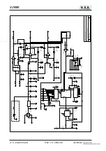
Страница 52: ...VJ1000 2 4 Power Supply Technical Appendix Rev 1 0 26 02 01 www DataSheet4U com ...

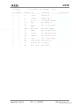
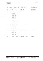
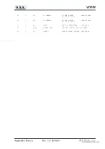
Страница 53: ... 3 1 C1 8µF 4KV HIGH VOLTAGE CAPACITOR COL4000V0008 4 2 F1 F2 F16A FAST FUSIBLE 16A FUS10 3X3825 5 1 CN1 CON CIR CON CIR 28P BULGIN F CNTBLCCF28P 28PF 6 1 MORS1 MORS 5 UK16 MORS 5 UK16 PHOENIX MORS5 UK16 7 1 J1 BNCFHT CONN BNC FEM PER HT CNTBNCFHT 8 1 TEL1 RLYFC10N TEL MATHSUSHITA FC10N TLR24AC420 9 1 TIM1 TMRPDX3M TIM MATS 24AC 2C 3M TMRPDX2C3AC24 10 1 SW1 PMS09 PULS 1V MS09 PIZZATO PLS1VMS09 11 ...

Страница 54: ...VJ1000 4 4 Power Supply Technical Appendix Rev 1 0 26 02 01 TEL1 F2 H T RECTIFIER BOARD R1 T1 C1 TRF1 R2 TIM1 F1 MORS1 PHOTO 4 FOTO 4 www DataSheet4U com ...

Страница 55: ...VJ1000 H T Rectifier Board 1 4 Appendice Tecnica Rev 1 0 26 02 01 www DataSheet4U com ...

Страница 56: ...VJ1000 2 4 H T Rectifier Board Technical Appendix Rev 1 0 26 02 01 www DataSheet4U com ...

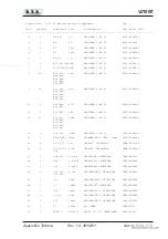
Страница 57: ...0KH0220 3 48 R1 R2 R3 100K RESISTOR 2W RSC002JH0100 R4 R5 R6 R7 R8 R9 R10 R11 R12 R13 R14 R15 R16 R17 R18 R19 R20 R21 R22 R23 R24 R25 R26 R27 R28 R29 R30 R31 R32 R33 R34 R35 R36 R37 R38 R39 R39 R40 R41 R42 R43 R44 R45 R46 R47 R48 4 24 C1 C2 C3 2N7 CERAMIC CAPACITOR CKM272BK600P C4 C5 C6 C7 C8 C9 C10 C11 C12 C13 C14 C15 C16 C17 C18 C19 C20 C21 C22 C23 C24 5 24 D1 D2 D3 SK3 17 SEMICRON DIODE 3A 1700...

Страница 58: ...VJ1000 4 4 H T Rectifier Board Technical Appendix Rev 1 0 26 02 01 Pagina lasciata intenzionalmente in bianco This page was intentionally left blank www DataSheet4U com ...

Страница 59: ...VJ1000 R F Block 1 4 Appendice Tecnica Rev 1 0 26 02 01 www DataSheet4U com ...

Страница 60: ...1 2 12 SP DIA 10 R S 1 2mm BFS12001210 15 1 L5 L1516RVR1 5 15 SP DIA 16 R S 1 5mm BFS15001516 16 1 L6 L1510RVR1 5 15 SP DIA 10 R S 1 5mm BFS15001510 17 1 L2 L210RVR1 5 2 SP DIA 10 R AR 1 5mm BFS15000210 18 1 L1 L338RVR1 33 SP DIAM 8 R S 1mm BFS10003308 19 1 MET1 STA250µA STRUMENTO 250µA SMABM55RQ251 20 1 CN3 MAMMUT 2P MORS MP MONT DIRET 2P MORMP2P 21 1 CN1 CON CIR CON CIR 28P BULGIN M CNTBLCCM28P ...

Страница 61: ...C MOTOR1 DC MOT BUHLER MOTRCVJ2000 1 61 013 325 W 36 1 M2 DC MOTOR2 DC MOT BUHLER MOTRPVJ2000 1 61 013 330 0 37 1 Q1 2N3055 NPN RF TRANSISTOR TRN2N3055 38 1 FAN1 BLOWER EBM1 VEN EBM G2E140 AC05 01VTLEBM 39 1 V1 3CX800 3CX800 EIMAC TRIODO VAL3CX800 www DataSheet4U com ...

Страница 62: ...VJ1000 4 4 R F Block Technical Appendix Rev 1 0 26 02 01 Pagina lasciata intenzionalmente in bianco This page was intentionally left blank www DataSheet4U com ...

Страница 63: ... Pressione della Turbina Calibration of the Fan Pressure Alarm Threshold p 31 R7 Taratura del R O S Calibration of the V S W R p 31 R21 Taratura dell Intervento della Protezione della Corrente di Griglia Calibration of the Grid Current Alarm Threshold p 32 www DataSheet4U com ...

Страница 64: ...2 4 7uF 25V R 1 5 100K R 1 9 100K D 2 1N4148 R 1 6 22K R 1 8 82K C 6 33uF 35V C 5 4n7 R 1 7 100K IC1B LM3900 2 3 4 14 7 C 1 8 0 47uF 25V R 2 0 22K R 2 4 22K R 2 5 82K R 2 6 100K cw R 2 1 T22K R 4 7 10K C 1 3 4 7uF 25V R 2 2 10 D 1 1N4148 D 9 D 1 0 D 1 1 D 1 2 D 1 3 D 1 4 C 7 4n7 C 8 33uF 35V C 1 9 0 47uF 25V R 2 7 100K R 2 8 22K R 4 9 10K R 5 1 10K R 5 0 10K R 2 3 100K D 4 1N4148 D 3 1N4148 R 3 0 ...

Страница 65: ... 47K RESISTOR 1 4W 5 RSC1 4JK0047 R48 R52 11 2 R18 R25 82K RESISTOR 1 4W 5 RSC1 4JK0082 12 10 R10 R11 100K RESISTOR 1 4W 5 RSC1 4JK0100 R12 R14 R15 R17 R19 R23 R26 R27 13 2 R34 R38 220K RESISTOR 1 4W 5 RSC1 4JK0220 14 3 R4 R7 R21 T22K TRIMMER REG VERT 10mm RVTD10VK0022 15 3 C3 C5 C7 4n7 CERAMIC CAPACITOR CKM472BK600P 16 4 C2 C4 C11 47nF CERAMIC CAPACITOR CKM473BK600P C14 17 2 C18 C19 0 47µF POLIES...

Страница 66: ...IS1N4001 30 1 W1 WL04 DIODE BRIDGE 1 5A PNRWL04 31 1 D20 Z6V8 ZENER DIODE 6 8V 0 4W DIZ6V80W4 32 1 IC5 7815 POS STABILIZER 1A CIL7815P 33 2 Q2 Q3 BC237 NPN TRANSISTOR TRNBC237 34 1 Q4 BD140 PNP TRANSISTOR TRNBD140 35 1 IC2 NE555 TIMER CIL555 36 2 IC3 IC4 4040 CMOS DIVIDER MOTOROLA CID4040 37 1 IC1 LM3900 NORTON QUAD AMP CILLM3900 38 1 D24 LEVE05 DIODE LED GREEN DIA 05 LEDVE05 www DataSheet4U com ...

Страница 67: ...Tecnica Rev 1 0 26 02 01 R1 Calibrazione della Misura di Corrente Anodica Calibration of the Anode Current Measurement p 33 R2 Calibrazione della Misura Corrente di Griglia Calibration of the Grid Current Measurement p 33 www DataSheet4U com ...

Страница 68: ...VJ1000 2 4 Grid Plate Meter B Technical Appendix Rev 1 0 26 02 01 www DataSheet4U com ...

Страница 69: ...________________________________________________ 1 1 R3 0 22 RESISTOR 5W RAF005JH0 22 2 1 R4 2 2 RESISTOR 5W RAF005JH02 2 3 2 R1 R2 T4K7 TRIMMER REG VERT 10mm RVTD10VK04 7 4 4 C2 C3 C4 C510nF CERAMIC CAPACITOR CKM103BK600P 5 1 C1 47nF CERAMIC CAPACITOR CKM473BK600P 6 1 MET2 STA250µA STRUMENTO 250µA SMABM55RQ251 7 1 CN1 MORS CS 10 MORS CS 10 CONT MORSLB10PPO 8 4 D1 D2 D3 D4BY255 SILICON DIODE 1000V...

Страница 70: ...VJ1000 4 4 Grid Plate Meter B Technical Appendix Rev 1 0 26 02 01 Pagina lasciata intenzionalmente in bianco This page was intentionally left blank www DataSheet4U com ...

Страница 71: ...VJ1000 Low Pass Filter 1 4 Appendice Tecnica Rev 1 0 26 02 01 C1 L1 C2 L2 C3 L3 C4 C5 L4 PHOTO 5 FOTO 5 www DataSheet4U com ...

Страница 72: ...VJ1000 2 4 Low Pass Filter Technical Appendix Rev 1 0 26 02 01 www DataSheet4U com ...

Страница 73: ...uantity Reference Part Description Part Order Code __________________________________________________________________________________________________ 1 2 C1 C5 27pFT COND BAND RAME TEFLON CBRT270RVR 2 3 C2 C3 C4 54pFT COND BAND RAME TEFLON CBRT540RVR 3 4 L1 L2 L3 L4L230RVR 2 SP DIA 30 BAND RAME BBR5000230 www DataSheet4U com ...

Страница 74: ...VJ1000 4 4 Low Pass Filter Technical Appendix Rev 1 0 26 02 01 Pagina lasciata intenzionalmente in bianco This page was intentionally left blank www DataSheet4U com ...

Страница 75: ...VJ1000 Input Matching Circuit 1 4 Appendice Tecnica Rev 1 0 26 02 01 www DataSheet4U com ...

Страница 76: ...VJ1000 2 4 Input Matching Circuit Technical Appendix Rev 1 0 26 02 01 www DataSheet4U com ...

Страница 77: ... Part Order Code __________________________________________________________________________________________________ 1 1 C2 T22pF TRIMMER CAPACITOR CVF220CK600 2 1 C1 27pF CERAMIC CAPACITOR NP0 CKM270BJ600C 3 1 C3 56pF CERAMIC CAPACITOR NP0 CKM560BJ600C 4 1 L1 L58RVR1 5 5 SP DIA 8 R AR 1 5mm BFS15000508 5 1 L2 L38RVR1 5 3 SP DIA 8 R AR 1 5mm BFS15000308 www DataSheet4U com ...

Страница 78: ...VJ1000 4 4 Input Matching Circuit Technical Appendix Rev 1 0 26 02 01 Pagina lasciata intenzionalmente in bianco This page was intentionally left blank www DataSheet4U com ...

Страница 79: ... 1 0 26 02 01 R6 Calibrazione della Lettura della Potenza Riflessa Calibration of the Measurement of the Reflected Power p 32 R9 Calibrazione della Lettura della Potenza Diretta Calibration of the Measurement of the Forward Power p 32 www DataSheet4U com ...

Страница 80: ...VJ1000 2 4 Directional Coupler Technical Appendix Rev 1 0 26 02 01 www DataSheet4U com ...

Страница 81: ..._ 1 2 R12 R13 47 RESISTOR 1 2W 5 RSC1 2JH0047 2 4 R1A R1B 100 RESISTOR 2W RSC002JH0100 R2A R2B 3 1 R3 8K2 RESISTOR 1 4W 5 RSC1 4JK08 2 4 2 R5 R8 22K RESISTOR 1 4W 5 RSC1 4JK0022 5 2 R6 R9 T22K TRIM REG VERT 10mm RVTD10VK0022 6 2 C5 C6 2p2 CERAMIC CAPACITOR NP0 CKM2 2BJ600C 7 1 C2 T2p22F TRIMMER CAPACITOR CVC2 22CK600 8 2 C3 C4 1nFPAS CERAMIC THROUGH CAP CDP102XK500 9 2 D1 D2 1N4148 SILICON DIODE D...

Страница 82: ...VJ1000 4 4 Directional Coupler Technical Appendix Rev 1 0 26 02 01 Pagina lasciata intenzionalmente in bianco This page was intentionally left blank www DataSheet4U com ...

Страница 83: ...VJ1000 Telemetry Card opt 1 4 Appendice Tecnica Rev 1 0 26 02 01 www DataSheet4U com ...

Страница 84: ...1 R 2 0 1M 1 R 2 1 1M 1 D 4 1N4005 D 3 1N4005 C 1 6 0 1uF C 1 7 470uF 35V JP2 MORS CS 10 1 2 3 4 5 6 7 8 9 10 C 2 8 0 1uF C 1 4 10uF 50V C 1 5 0 1uF U 5 7812 VI G N D V O C 3 0 0 1uF C 3 1 0 1uF C 1 FEMI C 3 FEMI C 4 FEMI C 5 FEMI C 2 FEMI C 6 FEMI C 2 9 FEMI C 7 FEMI U 1 B L M 3 5 8 N 5 6 7 R 2 2 1K 1 U1A L M 3 5 8 N 3 2 1 4 8 U2A L M 3 5 8 N 3 2 1 4 8 C 9 0 1uF U 2 B L M 3 5 8 N 5 6 7 R 2 3 1K 1...

Страница 85: ... R40 11 2 R33 R34 21K5 1 RESISTOR 1 4W 1 RSM1 4FK21 5 12 5 R9 R10 R11 100K RESISTOR 1 4W 5 RSC1 4JK0100 R12 R39 13 12 R1 R2 R3 1M 1 RESISTOR 1 4W 1 RSM1 4FM0001 R4 R5 R6 R7 R8 R19 R20 R21 R47 14 1 R36 TC20K TRIM REG VERT CERMET RVTVERVK0020 15 2 R13 R14 TC100K TRIM REG VERT CERMET RVTCERVK0100 16 20 C8 C9 C10 0 1µF CERAMIC CAPACITOR CKM104BK600P C11 C12 C15 C16 C18 C19 C20 C21 C22 C23 C24 C25 C26 ...

Страница 86: ...CON DIODE 600V DIS1N4005 D5 D6 27 1 D1 Z5V1 ZENER DIODE 5 1V 0 4W DIZ5V10W4 28 1 D7 Z9V1 ZENER DIODE 9 1V 0 4W DIZ9V10W4 29 1 Q1 BC237 NPN TRANSISTOR TRNBC237 30 4 U1 U2 U3 U4 LM358N DOUBLE OP AMP CILLM358N 31 1 U5 7812 POS STABILIZER 1A CIL7812P 32 1 R16 N C NOT CONNECTED www DataSheet4U com ...
Отзывы: