


VJ1000
32 / 40
USER MANUAL
Rev. 3.0 - 26/02/01
N.B. Several attempts may be necessary. At least 60 seconds should be allowed
inbetween attempts to allow an automatic reset.
3)
CALIBRATION OF THE GRID CURRENT (IG) ALARM THRESHOLD
a)
Connect the unit to the line supply and connect a dummy load (50Ohms 1.5KW).
b)
Switch the ST.BY. switch (15 Fig.1) to ST.BY.
c)
Wait for the fan to build up pressure.
d)
Perform the SETUP 3 procedure and steps required to calibrate the grid current IG
(paragraph 5.5).
e)
Adjust the reading (regulating the supply) to 22 mA.
f)
Adjust trimmer R21 until the IG protection is activated i.e. when the IG indicator (12
Fig.1) comes on.
g)
Reduce the indicated current to 10 mA.
h)
Wait for the automatic protection cycle to complete and repeat step e) to verify the
correct alarm threshold (22 mA).
8.3
Calibration of the PWR Meter (REF)
Perform the calibration procedure for the V.S.W.R. protection upto step b) (paragraph
5.2 (2)).
At this point verify that the VJ1000 meter reading is correct; adjustment may be made with
trimer R6 situated in the directional coupler on the output of the low-pass filter, near the
antenna connector.
To gain access to it, remove the small protection cover.
8.4
Calibration of the PWR Meter (FWD)
Perform SETUP 2 (Fig.4).
1)
Connect a 50 Ohm 1.5KW dummy load in series with a bypass wattmeter (Byrd model
43), switch on the amplifier and verify the correct reading of the VJ1000’s meter.
2)
Adjust trimmer R9, situated inside the directional coupler on the output of the low-pass
filter, near the antenna connector.
3)
To gain access, remove the small protection cover.
N.B. The trimmer R2 connected in series with the meter allows small adjustments
after the calibration of PWR, REF and FWD, and is normally in a central position.
www.DataSheet4U.com
Содержание VJ1000
Страница 1: ...Prodotto da Italia VJ1000 User Manual www DataSheet4U com ...
Страница 18: ...VJ1000 14 40 USER MANUAL Rev 3 0 26 02 01 FIG 1 www DataSheet4U com ...
Страница 20: ...VJ1000 16 40 USER MANUAL Rev 3 0 26 02 01 FIG 2 www DataSheet4U com ...
Страница 22: ...VJ1000 18 40 USER MANUAL Rev 3 0 26 02 01 PHOTO 1 3 1 2 5 7 11 9 4 6 8 12 10 www DataSheet4U com ...
Страница 24: ...VJ1000 20 40 USER MANUAL Rev 3 0 26 02 01 PHOTO 2 1 2 3 4 5 6 www DataSheet4U com ...
Страница 26: ...VJ1000 22 40 USER MANUAL Rev 3 0 26 02 01 PHOTO 3 6 1 2 5 4 3 w w w D a t a S h e e t 4 U c o m ...
Страница 38: ...VJ1000 34 40 USER MANUAL Rev 3 0 26 02 01 SETUP 1 FIG 3 www DataSheet4U com ...
Страница 39: ...VJ1000 35 40 USER MANUAL Rev 3 0 26 02 01 SETUP 2 FIG 4 www DataSheet4U com ...
Страница 40: ...VJ1000 36 40 USER MANUAL Rev 3 0 26 02 01 SETUP 3 FIG 5 www DataSheet4U com ...
Страница 44: ...VJ1000 40 40 USER MANUAL Rev 3 0 26 02 01 This page intentionally left blank www DataSheet4U com ...
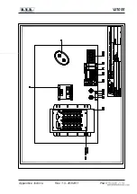
Страница 47: ...VJ1000 Flat Cable 1 2 Appendice Tecnica Rev 1 0 26 02 01 www DataSheet4U com ...
Страница 49: ...VJ1000 Telemetry Cable 1 2 Appendice Tecnica Rev 1 1 26 02 01 www DataSheet4U com ...
Страница 51: ...VJ1000 Power Supply 1 4 Appendice Tecnica Rev 1 0 26 02 01 www DataSheet4U com ...
Страница 52: ...VJ1000 2 4 Power Supply Technical Appendix Rev 1 0 26 02 01 www DataSheet4U com ...
Страница 55: ...VJ1000 H T Rectifier Board 1 4 Appendice Tecnica Rev 1 0 26 02 01 www DataSheet4U com ...
Страница 56: ...VJ1000 2 4 H T Rectifier Board Technical Appendix Rev 1 0 26 02 01 www DataSheet4U com ...
Страница 59: ...VJ1000 R F Block 1 4 Appendice Tecnica Rev 1 0 26 02 01 www DataSheet4U com ...
Страница 68: ...VJ1000 2 4 Grid Plate Meter B Technical Appendix Rev 1 0 26 02 01 www DataSheet4U com ...
Страница 72: ...VJ1000 2 4 Low Pass Filter Technical Appendix Rev 1 0 26 02 01 www DataSheet4U com ...
Страница 75: ...VJ1000 Input Matching Circuit 1 4 Appendice Tecnica Rev 1 0 26 02 01 www DataSheet4U com ...
Страница 76: ...VJ1000 2 4 Input Matching Circuit Technical Appendix Rev 1 0 26 02 01 www DataSheet4U com ...
Страница 80: ...VJ1000 2 4 Directional Coupler Technical Appendix Rev 1 0 26 02 01 www DataSheet4U com ...
Страница 83: ...VJ1000 Telemetry Card opt 1 4 Appendice Tecnica Rev 1 0 26 02 01 www DataSheet4U com ...


