VJ1000
38 / 40
USER MANUAL
Rev. 3.0 - 26/02/01
10. Telemetry Card Option
10.1
Calibration of the Voltages on the Telemetry connector
The VJ’s internal Telemetry connector gives to the external the voltages referred
to the various values under control. The voltage related to the Forward Power
output is 1,6V for 1KW. To calibrate this voltage follow the procedure below:
1-
Adjust the power of the machine to the nominal value of 1KW.
2-
Adjust R13 on the Telemetry Card to obtain a voltage, between pin 16 and
pin 1 of Telemetry connector, of 1,6V.
The pin 4 gives the voltage referred to measurment of the Reflected Power. This
voltage is 1,4V for 100W (10% of 1KW). To calibrate this voltage follow the
procedure below:
1-
Adjust the Reflected Power to 100W using a wattmeter Bird in output.
2-
Adjust R14 of Telemetry Card to obtain a voltage, between pin 14 and pin 1
of connector, of 1,4V.
3-
Adjust R36 to set the Power Good threshold.
10.2
Wiring Connections details
1- The exciter is not supplied from the Service Connector but separataly. This is
because if there was no high voltage, the Service Connector would be not
supplies instead, too. The exciter shall be ever ON.
2- A system that closes to earth a BNC contact when the machine is in Standby
mode is used. This contact is connected with a BNC-BNC cable to the Interlock/
RF Mute connector of the exciter. When the VJ goes in Standby status, the
exciter enters in RF Mute mode. The contact that permits this functionallity is
located on the Service teleswitch.
3- A Reset (or Restart) button is connected between pin 9 and earth of Telemetry
Card JP2 connector and it’s located on the front panel. It’s used to give the
same kind of signal as the an exciter that an PTXLCD gives when it is switches
ON. This operation resets the alarms and the remote control relay, in case the
amplifier is in OFF status and there is not an exciter able to change it to the ON
status.
4- The Alarms Card is supplied by the alternate current that first passes throught
JP3 (pin 1 and 2) of telemetry. When the Telemetry Card receives the REMOTE
OFF command, Alarms Card turns OFF itself. This permits to remotly reset the
alarms throught an ON-OFF-ON sequency. Please remember that after 6
attempts failed the machine will block itself. This remote control system gives
a remote reactivation mechanism.
5- A green LED is mounted between the point S of the Alarm Card and ground
(throught a 2K2 resistor); this is to indicate whether the Alarms Cards is supplied
www.DataSheet4U.com
Содержание VJ1000
Страница 1: ...Prodotto da Italia VJ1000 User Manual www DataSheet4U com ...
Страница 18: ...VJ1000 14 40 USER MANUAL Rev 3 0 26 02 01 FIG 1 www DataSheet4U com ...
Страница 20: ...VJ1000 16 40 USER MANUAL Rev 3 0 26 02 01 FIG 2 www DataSheet4U com ...
Страница 22: ...VJ1000 18 40 USER MANUAL Rev 3 0 26 02 01 PHOTO 1 3 1 2 5 7 11 9 4 6 8 12 10 www DataSheet4U com ...
Страница 24: ...VJ1000 20 40 USER MANUAL Rev 3 0 26 02 01 PHOTO 2 1 2 3 4 5 6 www DataSheet4U com ...
Страница 26: ...VJ1000 22 40 USER MANUAL Rev 3 0 26 02 01 PHOTO 3 6 1 2 5 4 3 w w w D a t a S h e e t 4 U c o m ...
Страница 38: ...VJ1000 34 40 USER MANUAL Rev 3 0 26 02 01 SETUP 1 FIG 3 www DataSheet4U com ...
Страница 39: ...VJ1000 35 40 USER MANUAL Rev 3 0 26 02 01 SETUP 2 FIG 4 www DataSheet4U com ...
Страница 40: ...VJ1000 36 40 USER MANUAL Rev 3 0 26 02 01 SETUP 3 FIG 5 www DataSheet4U com ...
Страница 44: ...VJ1000 40 40 USER MANUAL Rev 3 0 26 02 01 This page intentionally left blank www DataSheet4U com ...
Страница 47: ...VJ1000 Flat Cable 1 2 Appendice Tecnica Rev 1 0 26 02 01 www DataSheet4U com ...
Страница 49: ...VJ1000 Telemetry Cable 1 2 Appendice Tecnica Rev 1 1 26 02 01 www DataSheet4U com ...
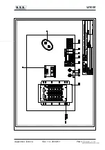
Страница 51: ...VJ1000 Power Supply 1 4 Appendice Tecnica Rev 1 0 26 02 01 www DataSheet4U com ...
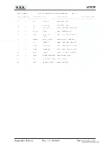
Страница 52: ...VJ1000 2 4 Power Supply Technical Appendix Rev 1 0 26 02 01 www DataSheet4U com ...
Страница 55: ...VJ1000 H T Rectifier Board 1 4 Appendice Tecnica Rev 1 0 26 02 01 www DataSheet4U com ...
Страница 56: ...VJ1000 2 4 H T Rectifier Board Technical Appendix Rev 1 0 26 02 01 www DataSheet4U com ...
Страница 59: ...VJ1000 R F Block 1 4 Appendice Tecnica Rev 1 0 26 02 01 www DataSheet4U com ...
Страница 68: ...VJ1000 2 4 Grid Plate Meter B Technical Appendix Rev 1 0 26 02 01 www DataSheet4U com ...
Страница 72: ...VJ1000 2 4 Low Pass Filter Technical Appendix Rev 1 0 26 02 01 www DataSheet4U com ...
Страница 75: ...VJ1000 Input Matching Circuit 1 4 Appendice Tecnica Rev 1 0 26 02 01 www DataSheet4U com ...
Страница 76: ...VJ1000 2 4 Input Matching Circuit Technical Appendix Rev 1 0 26 02 01 www DataSheet4U com ...
Страница 80: ...VJ1000 2 4 Directional Coupler Technical Appendix Rev 1 0 26 02 01 www DataSheet4U com ...
Страница 83: ...VJ1000 Telemetry Card opt 1 4 Appendice Tecnica Rev 1 0 26 02 01 www DataSheet4U com ...


