Ruijie Networks RG-AP820-L Скачать руководство пользователя страница 35

Hardware Installation and Reference Guide   


Appendix   

27


Appendix   

7.1   

Connectors and Media 

1000BASE-T/100BASE-TX/10BASE-T 

The  1000BASE-T/100BASE-TX/10BASE-T  is a  10/100/1000 Mbps  auto-negotiation port  that  supports auto 

MDI/MDIX. 

Compliant with IEEE 802.3ab, 1000BASE-T requires Category 5e 100-ohm UTP or STP (STP is recommended) 

with a maximum distance of 100 meters (328 feet). 

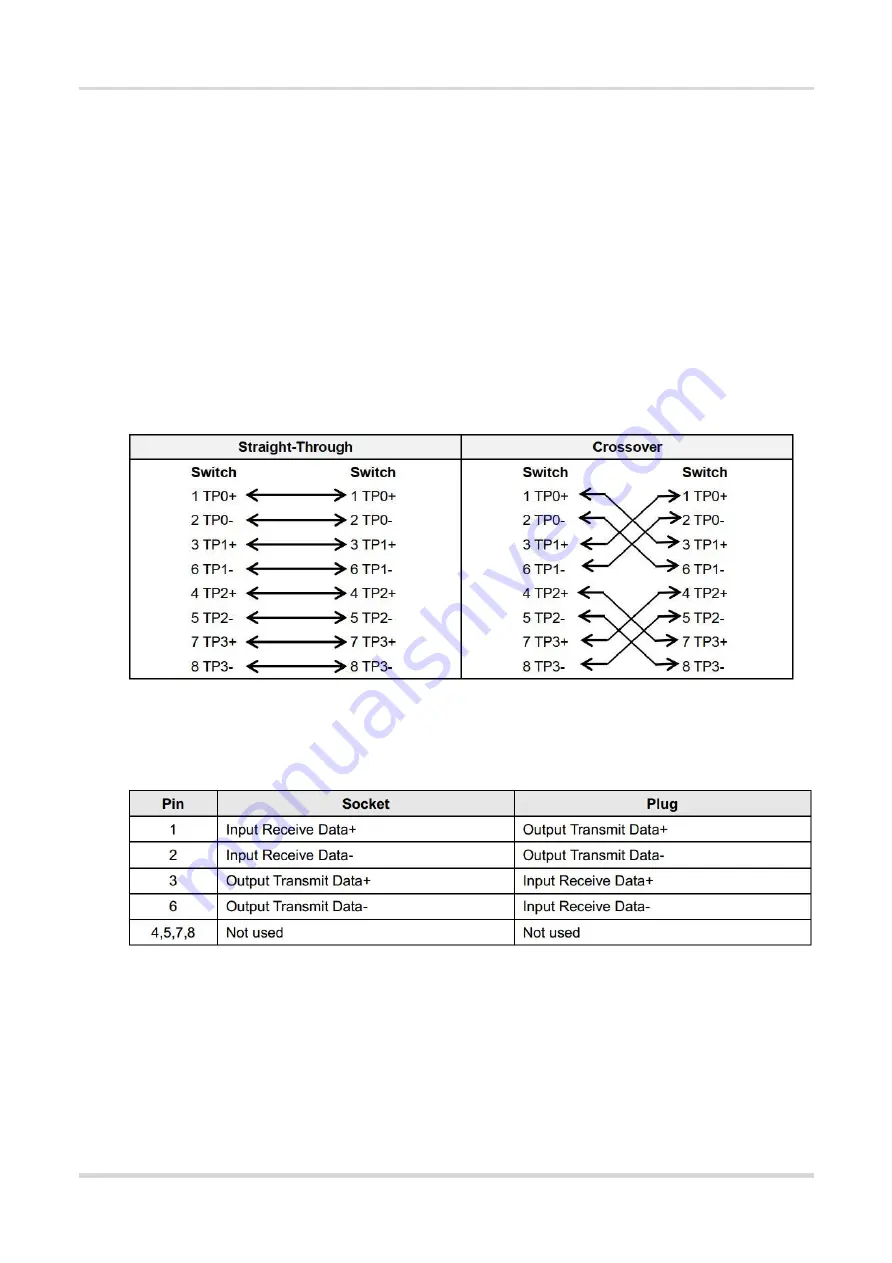
1000BASE-T requires all four pairs of wires be connected for data transmission, a s shown i

Figure 7-1

.   

Figure  7-1 1000BASE-T Connection 


10BASE-T uses Category 3, 4, 5 100-ohm UTP/STP and 1000BASE-T uses Category 5 100-ohm UTP/STP for 

connections. Both support a  maximum length of  100 meters

Figure  7-2

  shows  100BASE-TX/10BASE-T  pin 

assignments. 

Figure  7-2 100BASE-TX/10BASE-T  Pin Assignments 


Figure  7-3

 shows wiring of straight-through and crossover cables for 100BASE-TX/10BASE-T. 


Содержание RG-AP820-L

Страница 1: ...Ruijie RG AP820 L V3 Access Point Hardware Installation and Reference Guide DocumentVersion V1 0 Date 2022 3 10 Copyright 2022 Ruijie Networks...

Страница 2: ...hase are subjectto commercial contracts and terms Some or all of the products services or features described in this documentmay not be within the scope of your purchase or use Unless otherwise agreed...

Страница 3: ...re described as follows Danger An alert that calls attention to safety operation instructions thatif not understood or followed when operating the device can resultin physical injury Warning An alert...

Страница 4: ...echnical specifications and specifications and usage guidelines for cables and connectors It is intended for the users who have some experience in installing and maintaining network hardware At the sa...

Страница 5: ...cifications 3 1 3 1 Size and Weight 3 1 3 2 RF 4 1 3 3 Ports 5 1 3 4 Power Supply 5 1 3 5 Environment and Reliability 6 1 4 LEDs and Button 6 1 5 SFP Modules 7 2 Preparing for Installation 9 2 1 Safet...

Страница 6: ...eanliness Requirements 10 2 2 6 Anti interference Requirements 11 2 2 7 Lightning Protection Requirements 12 2 2 8 Inspection of the Installation Site 12 2 3 Tools 12 3 Installing the Access Point 13...

Страница 7: ...king after Installation 21 3 10 1 Checking Cable Connection 21 3 10 2 Checking Power Supply 22 4 Verifying Operating Status 23 4 1 Optional Configuring the Environment 23 4 2 Powering up the AP 23 4 2...

Страница 8: ...thernet port is not working after the Ethernet cable is plugged in 26 6 2 3 Wireless client cannot find the AP 26 6 2 4 LED keeps blinking red 26 6 2 5 LED keeps blinking green 26 6 2 6 LED keeps blin...

Страница 9: ...Gbps with up to 574 Mbps in the 2 4 GHz band and 2 402 Gbps in the 5 GHz band Designed for flexible deployments in the field ofeducation government finance and business the RG AP820 L V3 AP offers one...

Страница 10: ...and Reference Guide Product Overview 2 Figure 1 2 Front Panel Table 1 1 Front Panel No Item Description 1 LED Indicate the operation status of device Figure 1 3 Side View Table 1 2 Side View No Button...

Страница 11: ...pportIEEE 802 3afstandard PoE power supply 6 DC power plug Connectto the DC power adapter to supply power to the AP 1 2 Package Contents Table 1 3 Package Contents Item Quantity RG AP820 L V3 Access P...

Страница 12: ...al streams Operating Frequency Radio1 802 11b g n ax 2 4 GHz 2 483 GHz HE40 Radio2 802 11a n ac ax 5 150 GHz 5 350 GHz HE80 HE160 802 11a n ac 5 470 GHz 5 725 GHz 5 725 GHz 5 850 GHz HE80 country spec...

Страница 13: ...m MCS11 11ax 160MHz 77dBm MCS0 50dBm MCS11 Wi Fi Coverage Radius 10 m 32 81 feet Note The Wi Fi coverage is related to the installation environmentofthe access point 1 3 3 Ports Table 1 6 Ports Item D...

Страница 14: ...ations GB 4943 1 2011 IEC 62368 1 EMC Certifications EN 300386 GB T 19286 2015 GB T 17618 2015 1 4 LEDs and Button Table 1 9 Fit AP State Frequency Meaning Off N A The AP is NOT receiving power or the...

Страница 15: ...ce Pressed for more than 3s Restore defaultsettings 1 5 SFP Modules The 2 5G SFP portof the AP supports both copper and fiber links The negotiationspeed mayvary with the SFP module type and the speeds...

Страница 16: ...ed negotiation When you use the transceiver module the speed ofthe AP the module and the port of peer device mustbe the same The SFP port and copper port can be multiplexed as a combo port If two port...

Страница 17: ...d transportation Keep the AP at least500 meters away from the ocean and do not face it towards the sea breeze Do not place the device in walking areas During the installation and maintenance do notwea...

Страница 18: ...g air inlets 2 2 3 Space Requirement Maintain a minimum clearance of 0 4 cm 15 75 in around the device to ensure proper cooling and ventilation 2 2 4 Temperature Humidity Requirements To ensure the no...

Страница 19: ...tected againstthe intrusion of harmful gases such as sulfur dioxide hydrogen sulfide nitrogen dioxide and chlorine gas Table 2 2 lists limitvalues for harmful gases Table 2 2 Requirements for Gases Ga...

Страница 20: ...e following conditions mustbe met Maintain a minimum clearance of 0 4 cm 15 75 in around the device to ensure proper cooling and ventilation The installation site allows for proper cooling and ventila...

Страница 21: ...ents are there and make sure that The installation position provides sufficientspace for heatdissipation The installation position meets the temperature and humidityrequirements ofthe device The power...

Страница 22: ...should meetthe requirements in Table 1 4 Figure 3 1 Mounting Bracket 3 3 Precautions To avoid damage to the AP observe the following safetyprecautions Do not power on the device during installation I...

Страница 23: ...he signal coverage of the ceiling mounted device is larger than that of the wall mounted device Please choose the ceiling mounting method first 3 4 1 Ceiling Mounting 1 Drill four 6 5 mm 0 26 in diame...

Страница 24: ...directions on the mounting bracketdepending on how you route the Ethernet cable The square feetshould fit easilyinto the mounting slots Do notforcibly push the AP into the slots After installation ver...

Страница 25: ...mounting holes on the bracket Figure 3 6 Aligning the Square Feet with the Mounting Holes Caution Install the Ethernetcables before mounting the AP on the bracket 3 Slide the AP into the holes in the...

Страница 26: ...o the slots After installation verify that the AP is securelyfastened 3 5 Securingthe Access Point 1 Loosen the screw on the mounting bracketand engage the security screw Figure 3 8 Engaging the Secur...

Страница 27: ...eference Guide Installing the Access Point 19 Caution Install the Ethernetcables before mounting the AP on the bracket 3 6 Installing the SFP Module 1 Insertthe SFP module Figure 3 10 Inserting the SF...

Страница 28: ...AP is installed on the ceiling hold the AP in your hands and slide itsideways and awayfrom the bracket in the LAN port direction Figure 3 12 Removing the Ceiling mounted AP 2 If the AP is installed on...

Страница 29: ...ly 3 9 Bundling Cables 3 9 1 Precautions Make sure the cable bundles are neatand orderly Bend twisted pairs naturallyor to a large radius close to the connector Do not over tighten cable bundle as it...

Страница 30: ...tion and Reference Guide Installing the Access Point 22 3 10 2 Checking Power Supply Make sure all power ports are properly connected and compliantwith safety requirement Make sure the AP is operation...

Страница 31: ...is connected to a PC verify that the PC and PoE switch are properly grounded 4 2 Poweringup the AP 4 2 1 Checking Environment before Power on Verify that the power supplyis properly connected Verify...

Страница 32: ...the device to remotely monitor the configurations and status of the AP Note You can log in to the AP via Telnetand use monitoring related commands to maintain the AP 5 2 Remote Maintenance If the AP...

Страница 33: ...ED does not light up after the AP is powered on If you use PoE power supply verify that the power source is IEEE 802 11af compliant and then verify that the cable is connected properly If you use a po...

Страница 34: ...green The AP performs initialization after power on During this period the LED keeps blinking green and does not turn solid until the initialization is completed Note If the blinking persists for an...

Страница 35: ...d with a maximum distance of100 meters 328 feet 1000BASE T requires all four pairs of wires be connected for data transmission as shown in Figure 7 1 Figure 7 1 1000BASE T Connection 10BASE T uses Cat...

Страница 36: ...Hardware Installation and Reference Guide Appendix 28 Figure 7 3 100BASE TX 10BASE T Connection...

Страница 37: ...Transmitted Light dBm Intensity of Received Light dBm min max min max 1310Tx 15 50Rx Single mode fiber No 9 3 18 Table 7 2 Cabling Specifications of the SFP Module Port Media Type Core Size m Cabling...

Страница 38: ...ed the bend radius should be 10 times the overall diameter The minimum bend radius of a high speed cable such as an SFP cable should be 5 times the overall diameter ofthe cable If the cable is constan...

Страница 39: ...osition where device operation is notaffected and no damages occur to the device and cables during debugging Do not bind power cords to the rails for moving parts Leave a certain length of the cable c...

Страница 40: ...rews to fasten terminals Bundle cables of the same type and running in the same direction into groups Keep cables clean and straight Cables shall be tied according to the following table Diameter of C...

Страница 41: ...7 4 Power Supply DC power adapter Input voltage 48 V Rated current 0 6 A Technical Specifications ofthe DC Power Connector Inner Diameter Outer Diameter Depth Polarity 2 0 mm 0 08 in 6 3 mm 0 25 in 9...

Отзывы: