


3. Installation Procedures
RuggedCom® RuggedMAX™
32
Installation Guide Rev 1.1
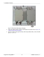
3.6.2. SFD Type Base Station
The power system is supplied by the operator.
Connect the power system DC output to the supplied connector.
Connect the other end (open end) of the supplied cable to the operator’s power system (according
to the labelling on the cable and the tables below).
Supplied Cable
Power Supply
Note
-48VDC
-48VDC
GND
+48VDC
+48VDC/ GND
“HOT Line”
GND
-48VDC/ GND
Connect -48V and GND
Table 3.4. +48 VDC Power System
Supplied Cable
Power Supply
Note
-48VDC
-48VDC
“HOT Line”
+48VDC
+48VDC/ GND
GND
GND
+48VDC/ GND
C48V and GND
Table 3.5. -48 VDC Power System
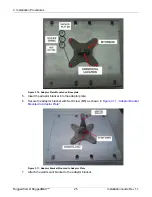
Figure 3.21, “Positive 48V Configuration”
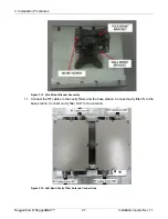
Figure 3.22, “Negative 48V Configuration”
show
+48V and -48V configurations.
Figure 3.21. Positive 48V Configuration
Figure 3.22. Negative 48V Configuration


