background image

- 12 -

REPAIR & REPLACEMENT

1.    After repairing any component:


a. check that electrical connections are correct and secure (see Figure 8),


b. remove any foreign material from enclosures,


c. install and secure all covers,


d. ensure that all fasteners are tight,


e. remove all foreign objects from heater, and


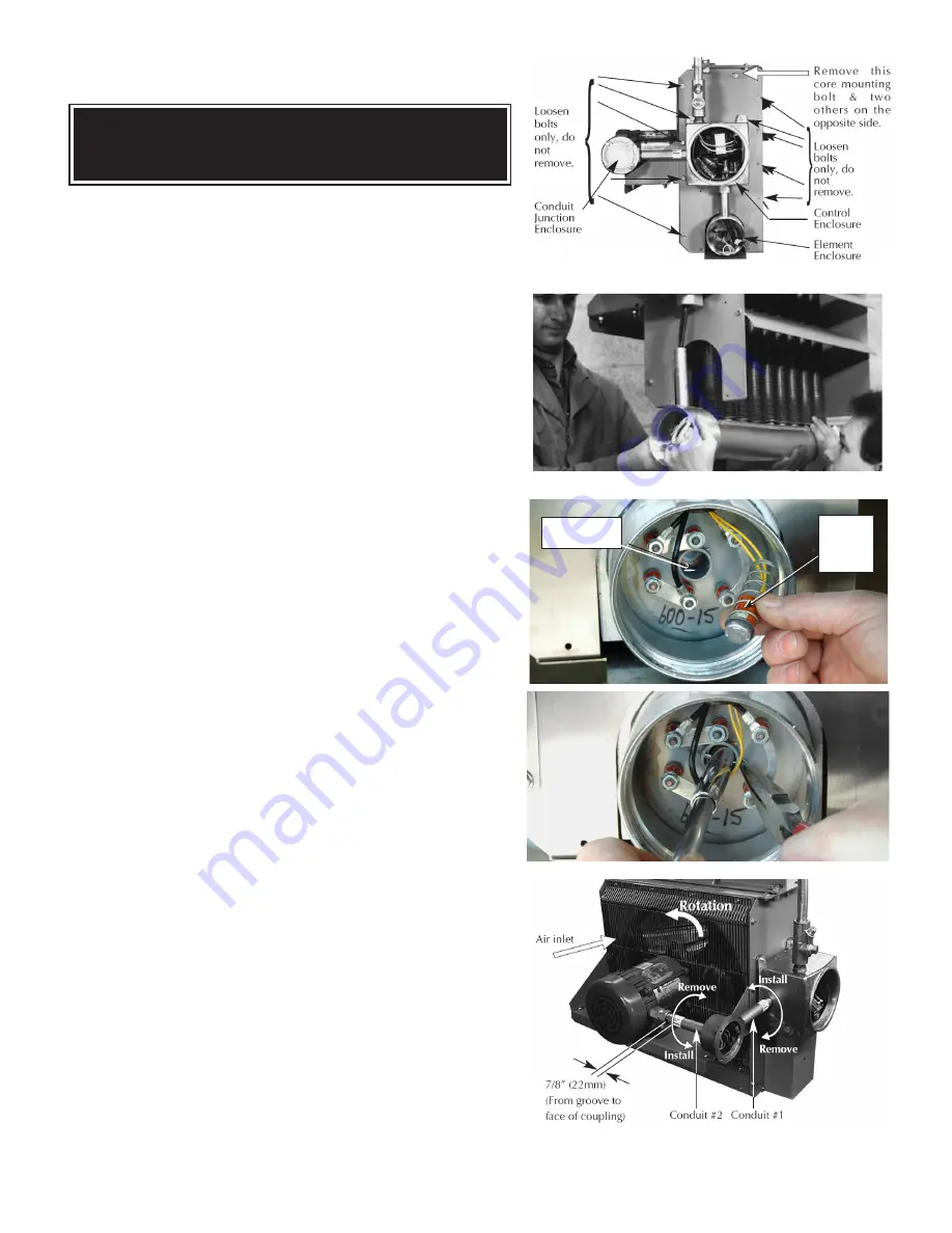
f.  ensure air exits through louvers and fan rotates counterclockwise when 


    viewed from rear of heater (see Figure 13).

C O R E

The heater core is vacuum charged and not field repairable. 

For core removal:

1.  Remove cabinet bottom and element enclosure cover. 

2.  Disconnect all wires entering element enclosure (see Figure 9).

3.  Slightly loosen all cabinet bolts shown in Figure 9, to prevent the core 

from binding.

4.  With an assistant supporting the weight of the core, remove the 3 core


mounting bolts. Carefully lower the core out of the cabinet (see Figure 

10).

5.  To return core to factory, use crate supplied with exchange core to protect


the element terminals and plate threads.

6.  To reinstall, lift the core up into cabinet while an assistant guides the


element wires into the element enclosure conduit.

7.  Position the core and tighten the 3 core mounting bolts. Tighten the


remaining cabinet bolts.

T E M P E R AT U R E   H I G H - L I M I T

1.  Remove temperature high-limit assembly and clean the inside of the 

thermowell (see Figure 11). A clean thermowell will ensure good thermal

 contact.

2.  Use only a factory supplied temperature high-limit to ensure safe operation. 

(refer to the instructions that accompany the replacement Temperature   

High-Limit kit).

3.  Reinstall the temperature high-limit assembly with the snap ring and spring


into the thermowell without damaging the insulating tube. Secure in place


with the cotter pin (see Figure 12).

MOTOR, FAN & FAN GUARD

1.  Remove bolts holding the motor to the motor mount.  On units with a built


in thermostat, remove the bolts on the back of the thermostat enclosure.

2.  Remove  conduit  #1  located  between  motor  junction   box  and  control 


enclosure  by turning  it  in the direction  illustrated  (see Figure 13). 


Note  conduits #1 and #2 are not interchangeable and have left hand threads on


one end, this end is indicated by a machined groove.

3.  Remove the 2 piece fan guard assembly (see Figure 14).

4.  Lift the motor assembly off the motor mount.

5.  Before removing the fan, measure and record the location of the fan hub on the


motor shaft (see Figure 15). If difficult to remove, use a gear puller on the fan hub.

6.  To reassemble, place motor assembly onto motor mount and fasten the fan guard


to cabinet.

7.  Simultaneously engage and tighten both ends of conduit #1 into enclosures.


Leave a 1/16” to 3/16” (1.6 to 4.8 mm) gap between the motor and fan guard (see


Figure 16). Adjust conduit #2 to center the fan in the shroud.

8.  To ensure a minimum 5 thread engagement, threaded ends of conduits must


protrude a minimum of 1/16” (1.6mm) into enclosures. The groove on conduit #2


must not be more than 7/8” (22mm) from motor coupling (see Figure 13).

9.  Bolt motor to motor mount.  Manually spin the fan blade to ensure fan rotates freely.

10.  Air must exit through louvers and fan must rotate counterclockwise when viewed


from rear of heater (see Figure 13).

FIGURE 13

FIGURE 12

FIGURE 11

FIGURE 10

FIGURE 9

3/32”

(2mm)

Drop

Thermowell

WARNING

Disconnect heater from power supply at fuse box before opening enclosures or 

servicing heater. Lock the switch in the “OFF” (open) position and/or tag the switch to 

prevent unexpected power application. 

Содержание FX4 Series

Страница 1: ...Temperature Code T3B 165 C 329 F 50 Hz 60 Hz Models For details of hazardous locations with potential for explosion refer to the Canadian Electrical Code Part 1 Section 18 or National Electrical Code articles 500 516 WARNING Read all important information notices Ruffneck and VacuCore are registered trademarks of Thermon Heating Systems Inc Copyright 2018 All rights reserved Part No 5031 Rev 15 06...

Страница 2: ...se rating and type are on printed circuit board Correct fuse must be in the active fuse clip It is recommended that a spare fuse be stored in the spare fuse clip Check all explosion proof conduits Replace damaged conduits All threaded conduit connections must have a minimum 5 turns engagement Straight threaded conduit must protrude a minimum of 1 16 1 6mm inside enclosures Taper threaded connectio...

Страница 3: ...ght position Refer to the Installation Mechanical section for details 12 Heater must be kept clean When operating in a dirty environment regularly clean the finned tubes fan and fan guard Follow the recommended maintenance procedures Refer to the Heater Maintenance Checklist section for details 13 The heater core is vacuum charged and contains propylene glycol If any fluid leakage occurs from the ...

Страница 4: ... that may impede the heater s air inlet or discharge 2 The air discharge is directed into open areas and not at occupants 3 The air discharge is not directed at a thermostat 4 The air discharge is directed across areas of heat loss such as doors and windows see Figure 1 5 The air discharge is directed along and at a slight angle toward exterior walls see Figure 1 6 If equipment freeze protection i...

Страница 5: ...ode fuse size shall be 125 of the line current or next size larger F I E L D W I R I N G 1 The supply conductors ground conductor and room thermostat conductors see point 2 page 4 all pass through the 1 NPT opening see Figure 4 and are to be wired into the control enclosure see Figure 5 2 Heater may be supplied with a factory installed built in room thermostat On heaters not supplied with this opt...

Страница 6: ...0 6 3 1 2 0 6 050 28 6 35 8 8 40 28 4 15 8 10412 3618 FX4 220150 084 220 8 4 1 2 0 8 140 38 2 47 8 6 50 37 9 21 1 10413 3618 FX4 220150 126 220 12 6 1 2 0 12 100 57 3 71 6 4 80 27 5 15 3 10424 3618 FX4 380350 025 380 2 5 3 0 7 2 260 3 8 4 8 14 15 19 7 11 0 10410 3618 FX4 380350 042 380 4 2 3 0 7 3 930 6 4 8 0 14 15 33 2 18 4 10411 3618 FX4 380350 063 380 6 3 3 0 7 6 020 9 6 12 0 14 15 28 4 15 8 10...

Страница 7: ...40 27 9 15 5 10412 3618 FX4 240360 075 240 7 5 3 1 4 7 200 18 0 22 5 10 25 27 9 15 5 10412 3618 FX4 480160 075 480 7 5 1 1 3 7 200 15 6 19 5 12 20 27 9 15 5 10416 3618 FX4 480360 075 480 7 5 3 0 7 7 200 9 0 11 3 14 15 27 9 15 5 10416 3618 FX4 600360 075 600 7 5 3 0 6 7 200 7 2 9 0 14 15 27 9 15 5 10420 3618 FX4 208160 100 208 10 1 2 7 9 690 48 1 60 1 4 70 37 2 20 6 10409 3619 FX4 208360 100 208 10...

Страница 8: ... will not enter Mounting Holes Two 9 16 in 14 3 mm diameter holes at top of heater Heating Elements Three long life low watt density high grade metal sheathed elements Temperature High Limit Automatic reset type snap action bimetal open on temperature rise Rated 100 000 cycles at 10 amps handles 0 128 amps Control Circuit 120 Volts 0 128 amps 15VA Grounded Optional Built in Thermostat Explosion pr...

Страница 9: ...ting Holes Two 9 16 in 14 3 mm diameter holes at top of heater Heating Elements Three long life low watt density high grade metal sheathed elements Temperature High Limit Automatic reset type snap action bimetal open on temperature rise Rated 100 000 cycles at 10 amps handles 0 130 amps Control Circuit 115 Volts 0 130 amps 15VA Grounded Optional Built in Thermostat Explosion proof 2 C to 28 C 36 F...

Страница 10: ...SEMBLY DIAGRAM HIGH LIMIT ASSEMBLY DIAGRAM Optional built in thermostat replaces item 16 1 4 22 23 24 5 6 7 8 9 10 11 12 13 14 15 16 17 2 9 19 20 21 25 26 30 31 32 27 28 29 3 18 33 BUS BAR CONFIGURATION ALL 1 PHASE MODELS BUS BAR CONFIGURATION ALL 3 PHASE 60 HERTZ 3 PHASE 50 HERTZ 415 VOLT MODEL BUS BAR CONFIGURATION 3 PHASE 380 VOLT 50 HERTZ MODELS ONLY ...

Страница 11: ...788 Bracket Motor Mount Left 14 3737 4590 3737 4590 3737 4590 Coupling Motor 15 3811 3812 3813 Conduit Motor 16 4983 4983 4983 Enclosure Conduit Junction 17 208 240V 60 HZ 1 PH 3813 220V 50 HZ 1 PH 3813 480V 60 HZ 1 PH 3813 ALL 3 PH 3813 3813 Conduit Control Enclosure 18 3810 3810 3810 Conduit Element Enclosure 19 3793 3793 3793 Enclosure Element 20 3510 3510 3510 Cover Element Enclosure 21 3790 3...

Страница 12: ...ring into the thermowell without damaging the insulating tube Secure in place with the cotter pin see Figure 12 MOTOR FAN FAN GUARD 1 Remove bolts holding the motor to the motor mount On units with a built in thermostat remove the bolts on the back of the thermostat enclosure 2 Remove conduit 1 located between motor junction box and control enclosure by turning it in the direction illustrated see ...

Страница 13: ... the same rating T R A N S F O R M E R 1 Replace with a factory supplied transformer of the same rating 2 On the new transformer select primary wires to match heater voltage Ensure that the correct transformer secondary lead is grounded see Figure 8 Individually terminate all unused wires using closed end connectors F U S E Replace fuse with one of the same type and rating as indicated on P C Boar...

Страница 14: ... 14 NOTES ...

Страница 15: ... 15 NOTES ...

Страница 16: ...y but not so as to limit the generality of the foregoing includes physical chemical or mechanical abuse accident improper installation of the product improper storage and handling of the product improper application or the misalignment of parts No warranty applies to paint finishes except for manufacturing defects apparent within 30 days from the date of installation The Company neither assumes no...

Отзывы: