background image

RTW DigitalMonitor 8ch 10689

47

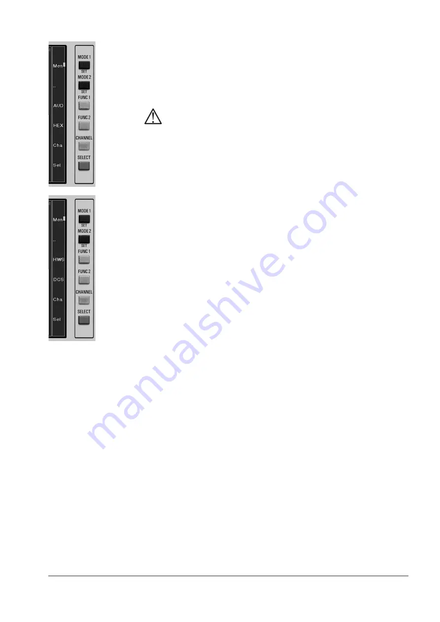
D 4.4.1. Tastenfunktionen im Anzeigemodus Channel Status

Durch Drücken und Festhalten der Taste „

SELECT

“ bei angezeigtem Kanal-

status-Display erhalten Sie Zugriff auf einige Sonderfunktionen. Die Tasten-
funktionen werden dabei in einer Spalte unmittelbar neben den Tasten an-
gezeigt, solange die Taste „

SELECT

“ festgehalten wird.

Hinweis:

Damit die korrekten Tastenbeschriftungen angezeigt werden, muss die Ka-
nalstatus-Anzeige im „

Multi Instrument 1

“ mit einem weißen Rahmen mar-

kiert sein, bevor die Taste „

SELECT

“ gedrückt und festgehalten wird. Ande-

renfalls werden stattdessen die Tastenfunktionen für eines der beiden an-
deren Instrumente angezeigt (und ausgeführt). Drücken Sie die Taste „

SE-

LECT

“ zunächst mehrfach kurz, um den weißen Rahmen auf das „

Multi

Instrument 1

“ zu bewegen.

• „AUD“/„HWS“

Diese Taste schaltet das Instrument zwischen den beiden Modi „

AUD

“ und

„

HWS

“ um.

• Der Modus „

AUD

“ zeigt die Aktivitäten der Audio-Datenbits der empfan-

genen Audio-Datenwörter im angewählten digitalen Eingangssignal an.
Wenn ein Bit in mehreren aufeinander folgenden Samples einen stati-
schen Wert von „0“ oder „1“ beibehält, wird es als inaktiv dargestellt.
Nachdem die Taste „

AUD

“ einmal gedrückt wurde, wird sie mit der Be-

zeichnung „

HWS

“ beschriftet.

• Der Modus „

HWS

“ schaltet das Instrument auf die Anzeige des Hard-

ware-Status’ um. Hier werden die physikalischen Parameter des gewähl-
ten digitalen Eingangssignals dargestellt.

• „DCS“/„HEX“

Diese Taste schaltet das Instrument zwischen den beiden Modi „

DCS

“ und

„

HEX

“ um.

• Im Modus „

DCS

“ werden die Channel-Status-Daten des gewählten di-

gitalen Eingangssignals als Klartext angezeigt. Nachdem die Taste
„

DCS

“ einmal gedrückt wurde, wird sie mit der Bezeichnung „

HEX

“

beschriftet.

• Der Modus „

HEX

“ schaltet das Instrument auf die Anzeige der Kanal-

status-Bytes des gewählten digitalen Eingangssignals im Hexadezi-
mal-Format um.

• „Cha“ (Channel)

Mit der Taste „

Cha

“ wird der physikalische Eingangskanal ausgewählt, der

für die Kanalstatus-Anzeige verwendet werden soll. Alle acht Eingangs-
kanäle 1A, 1B, 2A, 2B, 3A, 3B, 4A und 4B sind einzeln durch mehrfaches
Drücken der Taste „

Cha

“ anwählbar.

D 4. Anzeigearten • D 4.4. Kanal-Statusanzeige

Содержание 10689

Страница 1: ...Bedienungsanleitung Operating Manual DigitalMonitor 8ch 10689 Be isp iel E xam ple 10 68 9 P LU S...

Страница 2: ...These instruments comply with and fall under category 9 Monitoring and control equipment of Annex 1B of the RoHS Directive 2002 95 EC CE Note The photos and graphics in this manual are provided to ill...

Страница 3: ...n und Umbenennen von Presets 29 D 3 6 Liste der Werkseinstellungen Factory Presets 31 D 3 7 Festlegen des Start Presets 32 D 3 8 Definition der Toggle Optionen f r Multi Instrument 1 33 D 4 Anzeigeart...

Страница 4: ...ment 2 more 64 D 5 2 7 1 more f r Primary Function AES Status 64 D 5 2 7 2 more f r Primary Function Stopwatch 64 D 5 3 Remote 65 D 5 4 General 66 D 6 Installation 69 D 6 1 Sicherheit 69 D 6 2 Inbetri...

Страница 5: ...3 7 Defining Power On Mode 123 E 3 8 Defining Toggle Options for Multi Instrument 1 124 E 4 Display Modes 125 E 4 1 PPM Display 125 E 4 1 1 Changing PPM parameters 126 E 4 1 2 Key functions in PPM di...

Страница 6: ...1 Safety information 157 E 6 2 First time operation 158 E 6 3 Connection 159 E 6 3 1 Connecting Input and Output Signal connection 159 E 6 3 2 Connecting Remote External function control connection 15...

Страница 7: ...DigitalMonitor 8ch 10689 Be isp iel 10 68 9 P LU S Bedienungsanleitung deutsch...

Страница 8: ...RTW DigitalMonitor 8ch 10689 8...

Страница 9: ...erwachung digitaler Stereo und Mehrkanal Audiosignale in unterschiedlichsten pro fessionellen Audio Applikationen wie Broadcast Pre und Post Production und Musikproduktion Die vom Anwender ausgew hlte...

Страница 10: ...ur und Beschreibung aller Men Parameter Kapitel D 6 Installation Informationen ber Anschl sse und Fernbedienung und zus tzliche wich tige Sicherheitsinformationen Kapitel D 7 Service Informationen ber...

Страница 11: ...tallieren und konfigurieren beach ten Sie sorgf ltig die folgenden Sicherheitshinweise um Verletzungen und Besch digungen des Ger tes oder angeschlossener Ger te zu verhindern Um einen m glichen Strom...

Страница 12: ...chen des Ger tes sauber und trocken Innerhalb des Ger tes befinden sich keine Teile die der Wartung durch den Benutzer bed rfen berlassen Sie Wartungsarbeiten stets nur dem Fach mann Entfernen Sie ke...

Страница 13: ...erpackung und pr fen Sie die Vollst ndigkeit des folgen den serienm igen Zubeh rs Empfohlenes optionales Zubeh r Ausstattungs optionen und Erweiterungen sind in einem weiteren Abschnitt aufgelistet D...

Страница 14: ...RTW DigitalMonitor 8ch 10689 14...

Страница 15: ...er Mulit Korrelator Au erdem kann hier eine Anzeige aller Status daten der digitalen Eingangssignale erfolgen Das links unten angeordnete kleinere Fenster Multi Instrument 2 siehe Bild D 2 1 zeigt tex...

Страница 16: ...u acht Kan le mit integrierter Lautheitsanzeige und Peakhold Stereo Kanalpaare sind jeweils mit einem Spot Korrelator gekennzeichnet der sich am un teren Ende zwischen oder links neben dem Bargraphen...

Страница 17: ...ajous Darstellung von Stereosignalen mit integriertem Korrelations gradmesser Bild D 2 3 Das Multi Instrument 1 links oben hervorgehoben mit wei em Rah men zeigt das Audio Vektorskop Lissajous im 4 x...

Страница 18: ...ereo Modus Multi Correlator Anzeigemodus mit bis zu vier Korrelationsgrad Anzeigen f r bis zu vier Stereo Kanalpaare Die obere Korrelationsgrad Anzeige stellt die Phasen beziehung des links in der PPM...

Страница 19: ...Instrument 1 links oben hervorgehoben mit wei em Rah men zeigt den Kanal Status AES Channel Status im 4 x Stereo Modus Details siehe Kapitel D 4 4 Detaillierte Anzeige der Statusdaten f r die digitale...

Страница 20: ...ulti Instrument 2 links unten hervorgehoben mit wei em Rah men zeigt den AES Status im 4 x Stereo Modus F r das Multi Instrument 2 kann der Anzeigemodus AES Status gew hlt werden In diesem Modus wird...

Страница 21: ...Stoppuhr verf gt auch ber eine Hold Funktion zum Ablesen von Zwischenzeiten Details siehe Kapitel D 4 6 Bild D 2 7 Das Multi Instrument 2 links unten hervorgehoben mit wei em Rah men zeigt die Stoppuh...

Страница 22: ...RTW DigitalMonitor 8ch 10689 22...

Страница 23: ...Siehe Kapitel D 3 4 Die Konfigurationsdaten und Darstellungsvarianten des DigitalMonitor 8ch 10689 werden in 8 Werkseinstellungen Factory Presets und 8 vom Anwen der ver nderbaren Benutzereinstellung...

Страница 24: ...s Men system aktiviert Details siehe Kapitel D 3 3 Tastenfunktionen und beschriftung Einige der Tasten am DigitalMonitor 8ch 10689 sind je nach Anzeigeart mit unterschiedlichen Funktionen belegt um be...

Страница 25: ...h 10689 Siehe Bild D 3 2 Siehe Kapitel D 5 4 Siehe Bild D 3 1 Halten Sie nun die bereits mit der gr nen Markierung gekennzeichnete MODE SET Taste l nger als 1 Sekunde gedr ckt um in das Men system f r...

Страница 26: ...der Taste Quit und dr cken Sie die andere MODE SET Taste kurz Danach k nnen Sie durch l ngeres Dr cken dieser Taste erneut ins Men wechseln und dort das gew nschte Preset f r diese MODE SET Taste lade...

Страница 27: ...zur Verf gung steht schalten Sie das Display innerhalb des Men systems in die n chst h here Ebene zur ck Taste Rgt Right rechts Mit dieser Taste die nur in den Untermen s Routing Label Color und Save...

Страница 28: ...richten des DigitalMonitor 8ch 10689 sollte deshalb das Laden eines Presets geh ren das die in Ihrer Systemumgebung ben tigte Eingangskanal Konfiguration reflektiert Die Namen der Factory Presets sind...

Страница 29: ...3 Nachdem Sie das Hauptmen oder eines der Untermen s mit der Taste Quit verlassen haben werden Sie auf der Men seite Save Preset siehe Bild D 3 3 zum Speichern Ihrer aktuellen Konfiguration aufgeforde...

Страница 30: ...reset mit einem eigenen Namen versehen wollen bewegen Sie den roten Cursor mit den Tasten Up oder Dwn zum Men punkt Pre set Name Das erste Zeichen des bisherigen Namens ist mit einer ecki gen Klammer...

Страница 31: ...P P n a K 2 x 1 t o p S r o t a l e r r o K n a K 2 x 2 t o p S r o t a l e r r o K n a K 2 x 3 t o p S r o t a l e r r o K n a K 2 x 4 t o p S r o t a l e r r o K e l n a K 2 e l n a K 4 e l n a K 6...

Страница 32: ...Up oder Dwn die Men Option General aus 3 W hlen Sie mit den Tasten Up oder Dwn die Men Option PowerOn Mode aus 4 W hlen Sie durch mehrfaches Dr cken der Taste Sel SELECT die gew n schte Option aus Wen...

Страница 33: ...ehe Kapitel D 3 6 und D 5 2 5 und diese Konfiguration in einem User Preset abspeichern Da die Toggle Einstellungen als Teil eines Presets gespeichert werden n dern sie sich nach dem Laden eines neuen...

Страница 34: ...gle Funktion angew hlt werden 5 Dr cken Sie die Taste Quit um das Men zu verlassen und speichern Sie die Konfigurations nderung mit der Option Press SEL to SAVE und der Taste Sel SELECT bevor Sie zum...

Страница 35: ...eits Anzeigen enthalten die als farblich abgesetzte Felder innerhalb jedes Bar graphen dargestellt werden D 4 Anzeigearten D 4 1 Digitale Multinorm Peakmeter PPM Anzeige Die Anordnung der Kan le erfol...

Страница 36: ...e set und w hlen Sie die Option durch Dr cken der Taste Sel SELECT aus 3 Markieren Sie mit den Tasten Up oder Dwn eine der folgenden Optionen Die Option PPM Mode erm glicht das Ver ndern der Kanal Kon...

Страница 37: ...t ren das beispiels weise von einem anderen Anwender ben tigt wird 7 Wenn Sie das Preset mit einem individuellen Namen versehen m chten verwenden Sie die Tasten Up oder Dwn um den Cursor auf die Men O...

Страница 38: ...ELECT zun chst mehrfach kurz um den wei en Rahmen auf die PPM Anzeige zu bewegen Mem Memory Speicher Die Taste Mem kann verwendet werden um kurzzeitig die Maximal Pegel werte seit dem letzten Speicher...

Страница 39: ...erholt gedr ckt wurde vorausgesetzt dass diese Anzeigeart vorher im Men Toggle Selection der gedr ckten MODE SET Taste aktiviert worden ist Hinweis N here Informationen zur Aktivierung bzw Deaktivieru...

Страница 40: ...SE LECT aus 3 Markieren Sie mit den Tasten Up oder Dwn die Option Primary Func tion f r Multi Instrument 1 Dr cken Sie die Taste Sel SELECT wie derholt bis Vectorscope angezeigt wird 4 Markieren Sie...

Страница 41: ...Preset mit einem individuellen Namen versehen m chten verwenden Sie die Tasten Up oder Dwn um den Cursor auf die Men Option Preset Name zu setzen Mit der Taste Sel SELECT bl ttern Sie durch alle verf...

Страница 42: ...en auf das Multi Instrument 1 zu bewegen M S Halten Sie SELECT gedr ckt damit die Tastenfunktionen angezeigt wer den Mit der Taste M S schalten Sie das Vektorskop zwischen dem X Y und dem M S Modus um...

Страница 43: ...Correlator wird im Multi Instrument 1 dargestellt nachdem eine MODE SET Taste wiederholt gedr ckt wurde vorausgesetzt dass die se Anzeigeart vorher im Men Toggle Selection der gedr ckten MODE SET Tas...

Страница 44: ...Sie mit den Tasten Up oder Dwn die Option Primary Func tion f r Multi Instrument 1 Dr cken Sie die Taste Sel SELECT wie derholt bis Multi Correlator angezeigt wird 4 Markieren Sie mit den Tasten Up o...

Страница 45: ...inem individuellen Namen versehen m chten verwenden Sie die Tasten Up oder Dwn um den Cursor auf die Men Option Preset Name zu setzen Mit der Taste Sel SELECT bl ttern Sie durch alle verf gbaren Buchs...

Страница 46: ...Instrument 1 dargestellt nachdem eine MODE SET Taste wiederholt gedr ckt wurde vorausgesetzt dass diese Anzeigeart vorher im Men Toggle Selection der gedr ckten MODE SET Taste aktiviert worden ist Hin...

Страница 47: ...tenw rter im angew hlten digitalen Eingangssignal an Wenn ein Bit in mehreren aufeinander folgenden Samples einen stati schen Wert von 0 oder 1 beibeh lt wird es als inaktiv dargestellt Nachdem die Ta...

Страница 48: ...nd Festhalten der Taste SELECT bei angezeigtem AES Statusmonitor erhalten Sie Zugriff auf die Eingangskanal Auswahl Die Tastenfunktion wird dabei in einer Spalte unmittelbar neben den Tasten an gezeig...

Страница 49: ...ten Tastenbeschriftungen angezeigt werden muss die Stoppuhr Anzeige Stopwatch im Multi Instrument 2 mit einem wei en Rahmen markiert sein bevor die Taste SELECT gedr ckt und festge halten wird Anderen...

Страница 50: ...RTW DigitalMonitor 8ch 10689 50...

Страница 51: ...itor 8ch 10689 in den Men Modus umschaltet und das Hauptmen anzeigt Alle Men Seiten haben einen blauen Hintergrund MODE SET l nger als 1 s Siehe Kapitel D 3 3 Bild D 5 1 Das Hauptmen des DigitalMonito...

Страница 52: ...e g n u r e d n s i e w n i H e m a N t e s e r P 1 F o e r e t S x 1 2 F o e r e t S x 2 3 F o e r e t S x 3 4 F o e r e t S x 4 5 F l e n n a h C 2 6 F l e n n a h C 4 7 F l e n n a h C 6 8 F l e n...

Страница 53: ...rations Optionen Der PPM Modus PPM Mode kann wenn rot markiert unmittelbar auf der Men seite Modify Preset mit der Taste Sel eingestellt werden w hrend alle brigen Optionen im Untermen der Option more...

Страница 54: ...ig 18 18dB 0 dB FS 18 dB Dig 20 40dB 0 dB FS 20 dB ARD 9 60dB 0 dB FS 9 dB qDIN 10 qDIN 5 qNordic qBRIIa qBRIIb qZoom 10dB qZoom 1dB Headroom dB 9 Definition des Headroom Felds oberhalb der Referenz F...

Страница 55: ...us Off Dig Errors Dr cken Sie die Taste Sel um in das Untermen zu ge langen Beschreibung siehe Kapitel D 5 2 2 2 Loudness Display On Lautheitsanzeige ein On oder aus Off Weighting Awt Rms Betriebsart...

Страница 56: ...dann die Taste Rgt um den Cursor nach rechts zu bewegen bis er die gew nschte Bargraph Position Anzahl der Positio nen abh ngig von der gew hlten Betriebsart markiert an der das Eingangs signal diese...

Страница 57: ...um ein Anzeigeelement zu markieren und die Taste Rgt um den Cursor nach rechts zu bewegen bis die gew nschte Bargraph Positi on erreicht ist deren Farbe ver ndert werden soll Dr cken Sie die Taste Sel...

Страница 58: ...ck OFF berpr fung der MUTE Konditionen digi tale Null Off aus Time Zeit Sample Time 50ms Zeitbereich in dem digitale Nullen auftreten d rfen bevor die Mute Anzeige aktiviert wird 50 ms 100 ms 200 ms 3...

Страница 59: ...p u a H s u d o M M P P n a K 2 x 1 t o p S r o t a l e r r o k n a K 2 x 2 t o p S r o t a l e r r o k n a K 2 x 3 t o p S r o t a l e r r o k n a K 2 x 4 t o p S r o t a l e r r o k e l n a K 2 e l...

Страница 60: ...1 more Abh ngig von der Einstellung f r Multi Instrument 1 Primary Function siehe Kapitel D 5 2 3 bietet die Option more im Untermen jeweils unterschiedliche Auswahlpunkte f r die gew hlten Instrumen...

Страница 61: ...schnell Fast oder langsam Slow Color VCS Yellow Vektorskop Farbe Yellow White Black Blue Green Cyan Red Magenta Grid Blue Vectorskop Raster Farbe Blue Green Cyan Red Magenta Yellow White Black Label...

Страница 62: ...Color 0 White Anzeigefarbe des Werts 0 White Black Blue Green Cyan Red Magenta Yellow Color Red Anzeigefarbe negative Werte Red Magenta Yellow White Black Blue Green Cyan Color Grid Blue Anzeigefarbe...

Страница 63: ...ument 1 anzuw hlen Dr cken Sie f r jeden Modus die Taste Sel um diesen Anzeige Modus an On oder abzuschalten Off Alle auf On gesetzten Modi stehen f r die Toggle Funktion zur Verf gung Vectorscope Off...

Страница 64: ...ent 2 Primary Function siehe Kapitel D 5 2 6 bietet die Option more im Untermen jeweils unter schiedliche Auswahlpunkte f r die gew hlten Instrumente Verwenden Sie die Tasten Up oder Dwn um die Option...

Страница 65: ...bzw deaktivieren Bei Auslieferung ist die Funktion aktiviert Men Option Keys MODE SET l nger als 1 s Up Dwn auf Remote Sel Inputs Keys Auswahl der Funktion der Steuereing nge mit Taste Sel Keys Tasten...

Страница 66: ...mer zur Freischal tung des Men s bei aktivierter Menu Lock Funktion Verf gbare Codes 1351 4214 2132 6542 4251 6512 4231 4611 Standby 10 Min Zeit bis zum Dimmen der Hinterleuchtung nach Unterschreiten...

Страница 67: ...Taste Sel White Black Blue Green Cyan Red Magenta Yellow Framecolor Focus off cyan Rahmen Farbe f r die nicht gew hlten Instru mente White Black Blue Green Cyan Red Magenta Yellow Show keys Temporary...

Страница 68: ...RTW DigitalMonitor 8ch 10689 68...

Страница 69: ...nt werden Blockieren Sie das Netzkabel oder Netzge r t nicht es muss f r den Anwender jederzeit erreichbar bleiben Betreiben Sie das Ger t niemals mit entfernten Deckel oder Frontblenden Verwenden Sie...

Страница 70: ...9 pol Sub D F Buchse auf der Ger ter ckseite an Die Steuer eing nge m ssen wie in Kapitel D 6 3 2 beschrieben beschaltet werden Schlie en Sie optional einen externen Standard VGA Monitor mit einem ge...

Страница 71: ...bzw Ausgang digital AES 3 3 kalt 22 Schirm Geh use 10 Ein bzw Ausgang digital AES 3 2 hei 23 Ein bzw Ausgang digital AES 3 2 kalt 11 Schirm Geh use 24 Ein bzw Ausgang digital AES 3 1 hei 12 Ein bzw A...

Страница 72: ...erwendung der RTW Netzteile 1171 R und 1175 R Diese Weitspannungsnetzteile sind f r den Gebrauch mit dem Digi talMonitor 8ch entwickelt verf gen ber den erforderlichen 4 poligen Klein spannungsstecker...

Страница 73: ...ung AES 3 Eingang 3 4 Terminierung AES 3 Eingang 4 ffnen des Geh uses siehe Kapitel D 7 3 D 6 Installation D 6 4 nderung der AES 3 Eingangs Terminierung D 6 4 nderung der AES 3 Eingangs Terminierung M...

Страница 74: ...RTW DigitalMonitor 8ch 10689 74...

Страница 75: ...usgef hrt werden die von RTW dazu autorisiert wurden Hinweis Unsachgem es Entfernen von Teilen aus dem Ger t oder Modifikatio nen am Ger t k nnen Sicherheitsrisiken verursachen und die EMI CE Konformi...

Страница 76: ...7 1 2 Legen Sie den DigitalMonitor 8ch mit dem Display nach unten auf die Arbeitsfl che Achten Sie darauf das Display nicht zu verkratzen oder zu besch digen 3 L sen Sie die vier Schrauben an der obe...

Страница 77: ...e defekte Display Einheit zur ck an RTW Zum Display Tausch gehen Sie wie folgt vor Hinweis Beachten Sie die Ma nahmen zum Schutz vor Zerst rung der Baugrup pen durch statische Aufladungen 1 Zum ffnen...

Страница 78: ...hen Aufladungen gesch tzten Platz Bild D 7 4 4 L sen Sie nun vorsichtig das andere Ende des flachen Display Kabels aus der Anschlussverbindung rechts oben auf der Display Platine Achten Sie darauf Ste...

Страница 79: ...a und dem Display aus dem Geh use B Bild D 7 6 Hinweis Beim Herausdr cken der Display Einheit wird die Skala vom Rah men abgel st Halten Sie zur Sicherheit eine Hand von au en auf das Display damit di...

Страница 80: ...ie die Gewindebolzen der Display Einheit genau in die L cher der Stege Achten Sie dabei auf den genauen Sitz der Dis play Platine Fixieren Sie die Display Einheit mit den sechs Unterleg scheiben und d...

Страница 81: ...ay nicht zu besch digen Drehen Sie das Geh use wieder zur ck in seine vorherige Position C Bild D 7 8 8 Nehmen Sie das flache Display Kabel A und platzieren Sie den zuletzt gel sten Steckverbinder exa...

Страница 82: ...Haupt platine so dass es ca 2 cm ber die Hauptplatine herausragt Achten Sie darauf dass das flache Display Kabel dabei nicht zwischen Platine und Halterung bzw Platine und Geh use eingeklemmt wird Bef...

Страница 83: ...fte der Anschlussleiste B Dr cken Sie ihn mit leichtem Druck fest C Achten Sie darauf den Anschlussverbinder und das flache Dis play Kabel nicht zu besch digen Bild D 7 11 12 Pr fen Sie wieder den Sit...

Страница 84: ...anach ist der Digi talMonitor 8ch wieder betriebsbereit nur 10689 PLUS Platzieren Sie an der hinteren Kante auf der Unterseite des Geh u ses mittig den Standfu und befestigen Sie ihn mit der Schraube...

Страница 85: ...RTW DigitalMonitor 8ch 10689 85 D 8 Zeichnungen D 8 1 Abmessungen D 8 Zeichnungen D 8 1 Abmessungen...

Страница 86: ...f r den Frontplatteneinbau nur f r 10689 Weitspannungsnetzteil 1175 R 100 240 V AC 24 DC 2 7 A passendes Netzanschlusskabel Kleinspannungsstecker 4 pol Weitspannungsnetzteil 1171 R 90 264 V AC 24 DC 6...

Страница 87: ...RTW DigitalMonitor 8ch 10689 87 D 8 Zeichnungen D 8 3 Ersatzteile D 8 3 Ersatzteile Bestellnummern sind in der Ersatzteilliste Abschnitt D 8 4 aufgef hrt...

Страница 88: ...Clip f r Sub D Buchsen 16396 VGA Geh use RAL 7024 165688 Sub D Aufnahmewinkel 165701 R ckwand RAL 7024 166584 Abdeckkappe f r Inverter 179582 Gummifu Allgemeine elektronische Teile 14078 Taster schwar...

Страница 89: ...hraube M 3 x 6 mm 160567 Zahnscheibe M 4 161222 Schraube M 4 x 10 mm 165966 Basisplatte 165988 Gelenk 179582 Gummifu D 8 4 2 Display und Skala Best Nr Beschreibung 129693 Geh use mit VGA Display 16721...

Страница 90: ...RTW DigitalMonitor 8ch 10689 90...

Страница 91: ...2 Uhr Blickwinkelbereich horizontal 60 typ vertikal 60 typ Kontrast 250 bei optimalem Blickwinkel Hinweis Die verwendeten Displays haben eine sehr hohe Aufl sung 640 x 480 Pixel Auch bei modernsten Fe...

Страница 92: ...nzeige oder Sample genau Digital Over Anzeige rote Leuchtfelder ber den Balken Ansprechschwelle FS FS 1LSB FS 2LSB 0 1 0 5 1 0 2 0 oder 3 0 dB FS Ansprechzeit 1 bis 15 Samples Wortbreite 16 bis 24 bit...

Страница 93: ...nformationen locked dekodierter AES EBU Status Parit t Validit t Steuer und Anzeigelemente Tasten MODE 1 Set MODE 2 Set FUNC 1 FUNC 2 CHAN SELECT Lieferumfang Modell 10689 DigitalMonitor 8ch RAL 7024...

Страница 94: ...RTW DigitalMonitor 8ch 10689 94 Anhang A Technische Daten...

Страница 95: ...e 106nn einschl aller Optionen auf das sich diese Erkl rung bezieht mit den folgenden Normen bzw normativen Dokumenten bereinstimmt EMV 89 336 EWG EN 50081 1 EN 55022 B gestrahlt EN 55022 B leitungsge...

Страница 96: ...RTW DigitalMonitor 8ch 10689 96...

Страница 97: ...D DC Filter 55 DCS 47 Dig Errors 55 58 Digital Over Anzeige 92 Digitale Ausg nge 91 Digitale Eing nge 91 digitale Skalen 92 Display 91 Display Tausch 77 E Eingangsimpedanz 91 Einschalten 23 F Factory...

Страница 98: ...R cklaufzeit 92 S Sampling frequency range 91 Scale 54 SELECT 24 Service 75 SET 23 Sicherheit 11 69 Sicherheitsbegriffe 11 Sicherheitssymbole 11 SPL 55 SPL Referenzwert 92 Spot Corr 55 Spot Korrelato...

Страница 99: ...DigitalMonitor 8ch 10689 Ex am ple 10 68 9 P LU S Operating Manual english...

Страница 100: ...RTW DigitalMonitor 8ch 10689 100...

Страница 101: ...for visualizing digi tal audio stereo and multichannel formats in several professional audio applications like broadcast pre and post production environments and music production The measuring functio...

Страница 102: ...overview and description of all menu options Chapter 6 Installation Information about connections remote control and important additional information about safety Chapter 7 Service Information about h...

Страница 103: ...10689 please study the following safety information carefully and observe all the recommen dations to avoid injury and prevent damage to this product or any products connected to it To prevent possibl...

Страница 104: ...ess written consent of RTW Modifications can cause both safety hazards and affect the unit s EMI CE conformity The DigitalMonitor 8ch 10689 is designed for indoor use only and may only be operated wit...

Страница 105: ...1 Package Content Model 10689 DigitalMonitor 8ch table top unit Counter plug for power supply This manual Model 10689 PLUS DigitalMonitor 8ch table top unit Table stand Plug in power supply This manua...

Страница 106: ...RTW DigitalMonitor 8ch 10689 106...

Страница 107: ...Multi Correlator It can as well show AES status data of the digital input signals in text format The smaller display section on the left Multi Instrument 2 see Fig E 2 1 is used for text based informa...

Страница 108: ...ard peak level bargraphs with peak hold and loudness indicator for up to 8 channels Stereo channel pairs normally are marked with a Spot Correlator on the lower left side of or between the bargraphs T...

Страница 109: ...nals This display mode also includes a phase meter correlator Fig E 2 3 The Multi Instrument 1 highlighted with a white frame showing the Vectorscope Lissajous in 4 x Stereo mode See Chapter E 4 2 for...

Страница 110: ...n 4 x Stereo mode Multi Correlator Display mode with up to four phase meters for up to four stereo channel pairs showing the phase relationship between the two channels of a ste reo channel pair The u...

Страница 111: ...trument 1 highlighted with a white frame showing the Channel Status in 4 x Stereo mode See Chapter E 4 4 for details An integrated Status Monitor for AES 3 signals displays all channel status data for...

Страница 112: ...ument 2 is highlighted by a white frame Fig E 2 6 The Multi Instrument 2 highlighted with a white frame showing the AES Status in 4 x Stereo mode A summary of the most relevant AES status data can be...

Страница 113: ...hown in this display mode includes a hold function for reading out intermediate results See Chapter E 4 6 for details Fig E 2 7 The Multi Instrument 2 highlighted with a white frame showing the Stopwa...

Страница 114: ...RTW DigitalMonitor 8ch 10689 114...

Страница 115: ...guration data and display modes of the DigitalMonitor 8ch 10689 are stored in 8 factory presets and 8 user presets see Chapter E 3 4 and E 3 5 The buttons MODE 1 SET and MODE 2 SET can be used to easi...

Страница 116: ...nu refer to Chapter E 3 3 for details Instrument functions and button key captions Some of the buttons on the DigitalMonitor 8ch 10689 have varying functions depending on the display mode These functi...

Страница 117: ...of the DigitalMonitor 8ch 10689 Example DigitalMonitor 8ch 10689 See Fig E 3 2 See Chapter E 5 4 See Fig E 3 1 Press and hold the MODE SET button marked with the green spot for more than 1 second to e...

Страница 118: ...ave the menu with Quit and press the other MODE SET button After this you can access the menu again by pressing the same MODE SET button for more than 1 second and select the preset for this mode Modi...

Страница 119: ...u can leave the current menu page and return to the previous page Rgt Right key This key is only available on the Routing Label Color and Save Preset menu pages Using this key moves the cursor one ste...

Страница 120: ...data in a user preset will be explained in Chapter E 3 5 One of the first things you might want to do while configuring the Digital Monitor 8ch 10689 is to load a preset that reflects your individual...

Страница 121: ...see Fig E 3 3 which prompts you to store the actual configuration to one of the user presets However there is one exception to this rule If you entered the main menu page to only select a new preset...

Страница 122: ...b d e i f i d o m e b y a m s t e s e r P y r o t c a F e t o n e s a e l P e m a n t e s e r P 1 F o e r e t S x 1 2 F o e r e t S x 2 3 F o e r e t S x 3 4 F o e r e t S x 4 5 F l e n n a h C 2 6 F...

Страница 123: ...u mode 2 Use Up or Dwn key to set the red menu focus on the General option and enter the selection by pressing the Sel SELECT key 3 Use Up or Dwn key to set the menu focus on the PowerOn Mode selectio...

Страница 124: ...3 5 The Toggle selection menu of the DigitalMonitor 8ch 10689 To change the Toggle Selection of a preset proceed as following 1 From normal display operation press and hold the currently marked MODE...

Страница 125: ...nd additional loudness indi cators that are shown as a spot inside each bargraph E 4 Display Modes E 4 1 PPM Display The order of the channels is adjusted automatically according to the selected forma...

Страница 126: ...CT key 3 Use Up or Dwn key to highlight one of the first two selections PPM Mode lets you change the channel configuration for the bargraphs by pressing the Sel SELECT key repeatedly when highlighted...

Страница 127: ...normal display operation of the DigitalMonitor 8ch 10689 with the new preset loaded E 4 1 2 Key functions in PPM display Pressing and holding the SELECT button in the PPM display gives access to some...

Страница 128: ...vided that it was activated in the Toggle Selection of this mode before and it is available for the respective mode Note Please refer to Chapter E 3 8 to learn about how to activate or deactivate cert...

Страница 129: ...T key Use Up or Dwn key to highlight the Primary Function option for Multi Instrument 1 Press the Sel SELECT key repeatedly until Vectorscope is shown 3 Use Up or Dwn key to highlight the more option...

Страница 130: ...sing and holding the SELECT button in the Vectorscope mode gives ac cess to some alternative display modes The functions of the keys are labeled in a column next to the buttons while holding SELECT No...

Страница 131: ...display will show up in the Multi Instrument 1 after pressing a MODE SET button repeatedly provided that it was activated in the Toggle Selection of this Mode before Note Please refer to Chapter E 3 8...

Страница 132: ...g the Sel SELECT key 3 Use Up or Dwn key to highlight the Primary Function option for Multi Instrument 1 Press the Sel SELECT key repeatedly until MultiCorrelator is shown 4 Use Up or Dwn key to highl...

Страница 133: ...If you would like to name your preset use Up or Dwn key to set the cursor on the Preset Name selection With the Sel SELECT key you can toggle through a bank of characters Once you have found the desir...

Страница 134: ...splay will show up in the Multi Instrument 1 after pres sing a MODE SET button repeatedly provided that it was activated in the Toggle Selection of this Mode before Note Please refer to Chapter E 3 8...

Страница 135: ...play of the recei ved audio data words in the selected digital input signal If a bit has a fixed value of 0 or 1 in several consecutive samples it will be shown as inactive After having pressed the bu...

Страница 136: ...Functions in AES Status mode Pressing and holding the SELECT button in the AES Status mode gives access to the channel selection The key function is labeled in a column next to the buttons while hold...

Страница 137: ...mn next to the buttons Note To access the right set of key functions the Multi Instrument 2 showing the Stopwatch display must be highlighted with a white frame before pressing and holding SELECT Othe...

Страница 138: ...RTW DigitalMonitor 8ch 10689 138...

Страница 139: ...e of the MODE SET buttons for more than 1 second All menus are indicated by blue background color MODE SET longer than 1 s See Chapters E 3 3 Fig E 5 1 The Main menu of the DigitalMonitor 8ch 10689 Us...

Страница 140: ...o e r e t S x 3 4 F o e r e t S x 4 5 F l e n n a h C 2 6 F l e n n a h C 4 7 F l e n n a h C 6 8 F l e n n a h C 8 s t e s e r P e h t n i d e n i f e d s a n o i t c e S r e t e M m a r g o r P k a...

Страница 141: ...r PPM Mode The PPM features many configuration options The PPM Mode can be changed directly in the Modify Preset Menu Screen with the Sel key while all other options can be accessed after pressing Sel...

Страница 142: ...Dig 18 18dB 0 dB FS 18 dB Dig 20 40dB 0 dB FS 20 dB ARD 9 60dB 0 dB FS 9 dB qDIN 10 qDIN 5 qNordic qBRIIa qBRIIb qZoom 10dB qZoom 1dB Headroom dB 9 Headroom field definition above reference color cha...

Страница 143: ...M display on off Dig Errors press Sel to enter the submenu description see Chap ter E 5 2 2 2 Loudness Display On Loudness display On or Off Weighting Awt Rms Operation mode for loudness A weighted RM...

Страница 144: ...y to highlight one of the input channels and press the Rgt key to move the cursor to the right until it marks the desired bargraph position on which the input signal of this chan nel should be display...

Страница 145: ...display element and press the Rgt key to move the cursor to the right until it marks the de sired bargraph position on which the color should be changed Press Sel repeatedly to cycle through all avail...

Страница 146: ...dB 3 0 dB Mute Check OFF Mute check condition digital zero OFF TIME see next line SAMPLE Time 50ms Sequence length for digital zeros before activating MUTE display 50 ms 100 ms 200 ms 300 ms Samples 5...

Страница 147: ...c n a h c 2 x 2 t o p s r o t a l e r r o c n a h c 2 x 3 t o p s r o t a l e r r o c n a h c 2 x 4 t o p s r o t a l e r r o c s l e n n a h c 2 s l e n n a h c 4 s l e n n a h c 6 s l e n n a h c 8...

Страница 148: ...to open according submenu E 5 2 4 Multi Instrument 1 more Depending on the selected instrument for the Multi Instrument 1 Primary Function the more submenu provides the respective menu items Use Up o...

Страница 149: ...Yellow Vectorscope color Yellow White Black Blue Green Cyan Red Magenta Grid Blue Vectorscope grid color Blue Green Cyan Red Magenta Yellow White Black Label Cyan Vectorscope label color Cyan Red Mag...

Страница 150: ...White Color of the 0 spot White Black Blue Green Cyan Red Magenta Yellow Color Red Color of the section Red Magenta Yellow White Black Blue Green Cyan Color Grid Blue Color of the Grid Blue Green Cya...

Страница 151: ...ment 1 On each selection use the Sel key to switch this display mode On or Off All modes switched to On will be available for the Toggle function Vectorscope Off Multi Correlator Off must be ON pri in...

Страница 152: ...ment for the Multi Instrument 2 Primary Function the more submenu provides the respective menu items Use Up or Dwn key to highlight the more option Press the Sel key to enter the submenu E 5 2 7 1 mor...

Страница 153: ...689 At deli very the function of the remote connector is activated menu option Keys MODE SET longer than 1 s Up Dwn to Remote Sel Inputs Keys Remote connector operating mode choose option with Sel Key...

Страница 154: ...ode selection to enable menu when menu lock is activated Code table 1351 4214 2132 6542 4251 6512 4231 4611 Standby 10 Min Time value until dimming of backlight display after input signal falls below...

Страница 155: ...ted instrument with Sel key White Black Blue Green Cyan Red Magenta Yellow Framecolor Focus off Cyan Frame color for unselected instruments White Black Blue Green Cyan Red Magenta Yellow Show keys Tem...

Страница 156: ...RTW DigitalMonitor 8ch 10689 156...

Страница 157: ...ct from the power source Do not block the power cord or power supply it must remain accessible to the user at all times Do not operate this product with cover plates or panels removed Use only fuse ty...

Страница 158: ...tion to the power supply unit Connect the optional external function controls to the REMOTE marked 9 pin Sub D F connector The function controls have to be wired as de scribed in Chapter E 6 3 2 Conne...

Страница 159: ...input resp output digital AES3 2 hot 23 input resp output digital AES3 2 cold 11 shield case 24 input resp output digital AES3 1 hot 12 input resp output digital AES3 1 cold 25 shield case E 6 3 2 Con...

Страница 160: ...use of the RTW 1171 R or 1175 R These wide voltage power supplies have been designed for use with the DigitalMonitor 8ch and provide the necessary locking 4 pin low voltage connector type Binder 710...

Страница 161: ...Using the DIP switch on the main pcb the AES 3 input termination can be changed On 1 2 3 4 110 Off High Z Factory set is 110 Open the unit see Chapter E 7 3 Fig E 6 2 Partitial view of the main pcb wi...

Страница 162: ...RTW DigitalMonitor 8ch 10689 162...

Страница 163: ...fied technician authorized by RTW Important Incorrect removal of any parts from the unit or any modifications to the unit may cause safety hazards and negatively affect the EMI CE conformity Please re...

Страница 164: ...move it from the case Fig E 7 1 2 Place the DigitalMonitor 8ch face down on the work bench Asure not to scratch or damage the display 3 Loose the four screws on the rear side upper flange Open the bac...

Страница 165: ...send back the faulty unit to RTW Proceed as follows to exchange the display Note When servicing it is very important to observe all standard ESD electro static discharge protection procedures 1 For o...

Страница 166: ...at a ESD protected place Fig E 7 4 4 Loose carefully the wide locker right above on the display pcb of the other side of the connecting flat cable Avoid damage of the locker and the connecting flat ca...

Страница 167: ...inside and the other hand outside carefully push the display assy B including the scale which thereby is loosened from the inner side to the front side out of the frame Fig E 7 6 Please send the unit...

Страница 168: ...readed bolts of the pcb exactly into the holes of the holder bases of the case Thereby carefully take notice of the exact adjustment Check the correct placement of the display pcb and fasten it with t...

Страница 169: ...lay or the pushbuttons Then rotate the unit horizontally back in its previous position C Fig E 7 8 8 Replace the last detached plug of the connecting flat cable A exactly between the two guiding pins...

Страница 170: ...sided gap of the pcb without clamping and may only stick out for about 1 2 cm maximum Avoid damage because of canting Now first fasten the main pcb with its three screws B then fasten the connector p...

Страница 171: ...he two guiding pins of the connector B Fasten it with slight pressure C Take care not to press or damage the flat cable Fig E 7 11 12 Check wiring and connections again 13 Place the backplane cover ba...

Страница 172: ...supply Check its functions The units are now ready for operation 10689 PLUS only Place centered the table stand to the rear flange of the bottom side of the case and fasten it with its screw Fig E 7 1...

Страница 173: ...RTW DigitalMonitor 8ch 10689 173 E 8 Drawings E 8 1 Mechanical Outlines E 8 Drawings E 8 1 Mechanical Outlines...

Страница 174: ...incl panel mounting kit 13713 for 10689 only Wide voltage power supply 1175 R 100 240 V AC 24 DC 2 7 A corresponding power cable locking 4 pin low voltage connector Wide voltage power supply 1171 R 90...

Страница 175: ...RTW DigitalMonitor 8ch 10689 175 E 8 Drawings E 8 3 Spare parts E 8 3 Spare parts Please refer to partlist section E 8 4 for spare part ordering information...

Страница 176: ...16174 U Clip for Sub D connectors 16396 VGA case RAL 7024 165688 Sub D mounting angle 165701 rear panel RAL 7024 166584 cap for inverter 179582 pad Common electronical parts 14078 pushbutton black 144...

Страница 177: ...AL 7024 16035 screw M 3 x 6 mm 160567 toothed washer M 4 161222 screw M 4 x 10 mm 165966 base plate 165988 hinge 179582 pad E 8 4 2 Display and Scale Part No Description 129693 case with VGA display 1...

Страница 178: ...RTW DigitalMonitor 8ch 10689 178...

Страница 179: ...ngle horizontal 60 typ vertical 60 typ Contrast 250 at reversal direction Note The built in display has a high resolution 640 x 480 pixel Even with the most advanced techniques a small number of pixel...

Страница 180: ...tal Over indicator red spot indicators above each bargraph Threshold FS FS 1LSB FS 2LSB 0 1 0 5 1 0 2 0 or 3 0 dB FS Attack time 1 to 15 samples Word width 16 to 24 bit Mute indicator red spot indicat...

Страница 181: ...tion locked decoded AES EBU status parity validity Controls and Display Elements Keys MODE 1 Set MODE 2 Set FUNC 1 FUNC 2 CHAN SELECT Items delivered Model 10689 DigitalMonitor 8ch graphite grey RAL 7...

Страница 182: ...RTW DigitalMonitor 8ch 10689 182...

Страница 183: ...ctive 89 336 EEC and Directive 73 23 ECC Compliance was demonstrated to the following specifications as listed in the official journal of the European Communities EMC 89 336 EEC EN 50081 1 Emissions E...

Страница 184: ...RTW DigitalMonitor 8ch 10689 184...

Страница 185: ...tput 179 Digital Over indicator 180 Display 179 display mode switching 115 Down key 119 Dwn 119 E Esc 119 Escape 119 F Factory Preset 120 Factory Presets 122 Fall back time 180 First time operation 15...

Страница 186: ...4 Rst 127 S Safety information 157 Safety Summary 103 157 Safety Symbols 103 Sampling frequency range 179 Save Preset screen 121 Scale 142 Scales digital 180 Scales quasi analog 180 Sel 119 Select key...

Отзывы: