background image

Einbau- und Betriebsanleitung 
Installation and Operating instructions 
 

SR3300-8010 


SR-3300 


Page  50 

07/2018 

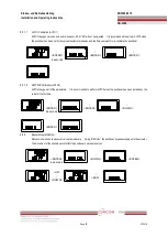
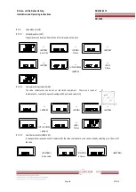
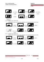
6.3.5.6


Split Range Mode (SPLIT)


The valve can be operated by split range control 

 4~12mA or 12~20mA.     


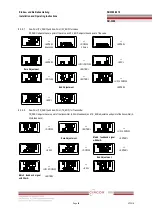
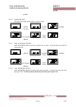
6.3.5.7


Custom Zero Setting Mode (CST ZERO)


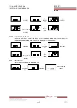
Custom Zero Setting Mode allows the user to set any specific point as zero position.    For example, the zero point can be set 

at input signal of 7mA.     

6.3.5.8


Custom End Setting Mode (CST ENd)


Custom End Setting Mode allows the user to set any specific point as end position.    For example, the end point can be set at 

input signal of 11mA.   

The difference between zero and end point must be greater or equal to 4mA.     


<ENTER> 


<ENTER> 
6 seconds 


<DOWN> 

5 times 


<ENTER> 


<UP>/<DOWN> 


<ESC> 
3 times 


<ENTER> 
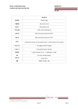


<ENTER>


<DOWN>


6 times


<ENTER>


<UP>/<DOWN>


<ESC>


3 times


<ENTER>


Содержание SR-3300

Страница 1: ...Einbau und Betriebsanleitung Installation and Operating instructions SR3300 8010 SR 3300 Page 1 07 2018...

Страница 2: ...2 Installation des SR 3300 4 Anschl sse 4 1 Sicherheit 4 2 Versorgungsdruck Bedingungen 4 3 Leitungssystem Bedingungen 4 4 Anschluss Antrieb 4 4 1 Einfachwirkender Antrieb SR 3300 4 5 Stromanschluss...

Страница 3: ...ales umgekehrtes Feedback TR_NORM REV 6 3 4 5 Normales umgekehrtes HART Signal HT_NORM REVS 6 3 5 Ventil Modus VALVE 6 3 5 1 Wirkrichtungs Einstellung ACT 6 3 5 2 Einstelloptionen CHAR 6 3 5 3 Benutze...

Страница 4: ...Allgemeines Der intelligente Stellungsregler der Serie SR 3300 dient der pr zisen Steuerung des Ventilhubs als Reaktion auf ein von der Steuervorrichtung ausgesendetes Eingangssignal von 4 bis 20 mA...

Страница 5: ...Typenschildbeschreibung SR 3300 Typenschild am Ger tegeh use Model Number Zeigt die Modellnummer des Stellungsreglers Explosion Proof Bezeichnet den zertifizierten Explosionsschutzgrad Input Signal Be...

Страница 6: ...T5 Umgebungstemperatur 30 85 Linearit t 0 5 F S Kabell nge 5 m Hysterese 0 5 FS Kabell nge 5 m Empfindlichkeit 0 2 FS Kabell nge 5 m Wiederholgenauigkeit 0 3 F S Kabell nge 5 m Durchflussleistung 70...

Страница 7: ...Einbau und Betriebsanleitung Installation and Operating instructions SR3300 8010 SR 3300 Page 7 07 2018 2 5 Einzelteile und Baugruppen SR 3300 SR 3300 Explosionsansicht...

Страница 8: ...agenteilen ist vor Beginn der Arbeiten das Ventil vollst ndig freizuschalten Medium und Hilfsenergie Achten Sie darauf dass der Stellantrieb vollst ndig entl ftet ist Beachten Sie bitte auch die Einba...

Страница 9: ...n so ein dass er eine horizontale Position einnimmt Eine unsachgem e Installation kann w hrend des Betriebs zu geringerer Linearit t und zu unn tigem Ventilpendeln f hren 2 Kontrollieren Sie den Venti...

Страница 10: ...tsprechen sauber lfrei und trocken sein Wir empfehlen stets einen Luftfilterregler zu verwenden 4 2 Versorgungsdruck Bedingungen Instrumentenluft deren Drucktaupunkt mindestens 10 K unter der niedrigs...

Страница 11: ...druckfest und vollst ndig dicht sein Der Leitungsdurchf hrungsanschlu ist PF oder G Stellen Sie vor dem Anschluss sicher dass das Ger t vollst ndig von der Stromversorgung getrennt ist ffnen Sie die...

Страница 12: ...der Widerstand niedriger als 100 Ohm sein muss 3 Verwenden Sie im Fall einer externen Erdung einen Schraubendreher um die Geh use Schrauben zu l sen 5 Einstellungen 5 1 Automatischer Manueller Schalt...

Страница 13: ...schen dem Ausgang OUT und dem Manometerblock eingebaut werden 6 Betrieb 6 1 Sicherheit Nachfolgend wird die Inbetriebnahme des Ventils und Antriebs beschrieben Bevor Sie eine AUTO Kalibrierung vornehm...

Страница 14: ...er Kegelspindel Ziffer 6 Run Err Fehler Unterschied zwischen SV F hrungssinal und PV Ventilhub Um das Display zu wechseln gleichzeitig die Tasten ESC UP dr cken Das Display wechselt in der oben angege...

Страница 15: ...librieren m chte 6 3 1 2 AUTO2 Kalibrierung AUTO2 AUTO2 ndert alle Parameter Es wird empfohlen AUTO2 durchzuf hren wenn der Stellungsregler am Ventil zum ersten Mal installiert wurde 6 3 2 Manueller M...

Страница 16: ...e ndert wurden werden sie gespeichert Zu diesem Zweck stellen Sie bitte sicher die Taste ENTER zu dr cken Nach Vornahme der nderungen besteht keine Notwendigkeit wieder zum RUN Modus zur ckzukehren um...

Страница 17: ...eller den Sollwert Gefahr der Instabilit t bei zu gro em Kp 6 3 3 3 D Wert Kd Differenzierfaktor Kd Der Regler reagiert auf nderungen der F hrungssignalgeschwindigkeit Je schneller sich das Signal nde...

Страница 18: ...KI_ Werte Die Prinzipien der P_ D_ und I_Werte sind dieselben wie die der P D und I Werte allerdings werden diese Werte aktiviert wenn der Fehlerprozentsatz innerhalb von 1 liegt 6 3 4 Handkalibrieru...

Страница 19: ...ers TR_ZERO stellt den Nullpunkt des Transmitters 4 20mA Feedback und TR_END den Endpunkt des Transmitters 4 20mA Feedback ein Nullpunkteinstellung ENTER DOWN ENTER UP DOWN Endeinstellung ENTER ESC DO...

Страница 20: ...Nullpunkts eingestellt werden Normales umgekehrtes Feedback TR_NORM REV Das R ckmelde Signal des Stellungsreglers kann normal oder gegenl ufig zum F hrungssignal eingestellt werden 6 3 5 Ventil Modus...

Страница 21: ...iebsarten zur Auswahl linear LIN gleichprozentig EQ und schnell ffnend QO 6 3 5 2 Benutzer Einstellungen USER SET Sollte f r den Stellungsregler eine frei definierbare Kennlinie ben tigt werden so kan...

Страница 22: ...Geschlossen Schlie en TSHUT CL Der Parameter TSHUT CL erm glicht es das Ventil bei 4 mA vollst ndig zu schlie en Wenn das Eingangssignal 4 mA erreicht wird die Luft bei Stellantrieben die ohne Luft s...

Страница 23: ...ngangssignal von 7mA eingestellt werden 6 3 5 9 Benutzerdefinierter Endpunkteinstell Modus CST ENd Der benutzerdefinierte Endpunkteinstell Modus erm glicht es dem Benutzer einen beliebigen Punkt als E...

Страница 24: ...Ventil pr zise steuern wenn der Winkelbereich des Feedback Hebels den vorgeschlagenen Winkelbereich bersteigt Der Stellungsregler kann den Fehler durch Interpolation verringern 6 3 6 Anzeige Modus VI...

Страница 25: ...Ventilstellung bei 25 ist bIAS 75 BIAS Wert wenn die Ventilstellung bei 75 ist 0Y 0d Verwendete Gesamtzeit Wenn eine Einheit weniger als 1 Minute verwendet wurde wird die Zeit nicht akkumuliert FULL_...

Страница 26: ...durch Achten Sie darauf dass der Feedback Hebel bei 0 und 100 nicht den Hebelanschlag ber hrt CHK AIR Das Ventil funktioniert nicht wenn der Stellungsregler w hrend der Auto Kalibrierung das Full Open...

Страница 27: ...t die verstrichene Zeit weniger als 1 Sekunde Die Gr e des Antriebs ist zu klein Verwenden Sie eine variable Blende Verwenden Sie einen gr eren Antrieb G Pv ist unter 100 Der Winkel des Feedback Hebel...

Страница 28: ...Einbau und Betriebsanleitung Installation and Operating instructions SR3300 8010 SR 3300 Page 28 07 2018 8 Parameter Struktur Contents...

Страница 29: ...3 Installation 3 1 Safety 3 2 SR 3300 Installation 4 Connections 4 1 Safety 4 2 Supply Pressure Condition 4 3 Piping Condition 4 4 Connection Actuator 4 4 1 Single acting actuator SR 3300 4 5 Connecti...

Страница 30: ...r 6 3 5 3 End Point Ratio for Valve PE_TRIM 6 3 5 4 Normal Reverse Feedback Signal TR_NORM REV 6 3 5 5 Normal Reverse HART Signal HT_NORM REVS 6 3 6 Valve Mode VALVE 6 3 6 1 Acting Adjustment ACT 6 3...

Страница 31: ...neral SR 3300 series Smart Positioner accurately controls valve stroke in response to an input signal of 4 20mA from the controller Built in micro processor optimizes the positioner s performance and...

Страница 32: ...2 3 Label Description SR 3300 Body Label Model Indicates the model number of the positioner Explosion Proof Indicates certified explosion proof grade Input Signal Indicates input signal range Operatin...

Страница 33: ...ia IIC T6 T5 Ambient Temp Operating Temp 30 85 Linearity 0 5 F S cable length 5 m Hysteresis 0 5 F S cable length 5 m Sensitivity 0 2 F S cable length 5 m Repeatability 0 3 F S cable length 5 m Flow...

Страница 34: ...Einbau und Betriebsanleitung Installation and Operating instructions SR3300 8010 SR 3300 Page 34 07 2018 2 5 Parts and Assembly SR 3300...

Страница 35: ...structions Any input or supply pressures to valve actuator and or to other related devices must be turned off Use bypass valve or other supportive equipment to avoid entire system shut down Ensure the...

Страница 36: ...feedback link bar to make parallel Improper installation may cause poor linearity and may create unnecessary hunting during the operation 6 Check the valve stroke The stroke marks are indicated on th...

Страница 37: ...ction pin 4 Connections 4 1 Safety Supply pressure should be clean and dry air avoiding moisture oil or dust Always recommended to use air filter regulator Young Tech Co Ltd has not tested positioner...

Страница 38: ...azardous and explosive gas area conduit tube or pressure proof packing union must be used The compound charging box should be the flameproof type and must be sealed completely Conduit entry connection...

Страница 39: ...terminal plate on the right hand bottom side of the terminal plate The outer cable entry is located at outside of the terminal Please make sure that the resistance is less than 100ohm 6 When using ex...

Страница 40: ...variable orifice can be inserted Operation 6 1 Safety Following process will operate valve and actuator Before proceed with any AUTO Calibration please separate valve from the entire system so AUTO Ca...

Страница 41: ...un Vel Velocity Current valve stem s velocity digit 14 Run Err Error Difference between SV and PV To change display push ESC UP buttons at the same time The display will change in the order indicated...

Страница 42: ...wants to re calibrate the positioner 6 3 1 2 AUTO2 Calibration AUTO2 AUTO2 changes all of the parameters It is recommended to perform AUTO2 when the positioner has been installed on the valve for the...

Страница 43: ...as soon as you save the value To save the changes please ensure to press ENTER button There is no need to go back to RUN mode after changes are being made to observe the changes 6 3 3 1 Dead Zone dEAd...

Страница 44: ...al compensation signal based on the percentage of error allowance As the value increase it is more likely to have hunting As the value decreases the positioner will move slowly to the target position...

Страница 45: ...Zero Point TR_ZERO and End Point TR_END for Transmitter TR_ZERO adjusts the zero point of the transmitter 4 20mA feedback and TR_END adjusts the end point of the transmitter 4 20mA feedback ENTER 6 s...

Страница 46: ...Einbau und Betriebsanleitung Installation and Operating instructions SR3300 8010 SR 3300 Page 46 07 2018...

Страница 47: ...ting operating is used End Point can be adjusted within 10 of total valve stroke without adjusting valve s zero point 6 3 4 4 Normal Reverse Feedback Signal TR_NORM REV The feedback signal from the po...

Страница 48: ...valve characteristic can be set on the field s requirement There are 3 types of characteristics linear LIN equal percentage EQ and quick open QO 6 3 5 3 User Characteristics USER SET In case position...

Страница 49: ...pen completely as the input signal reaches around 20mA 6 3 5 5 Tight Shut Close TSHUT CL Tight Shut Close allows the valve to close completely as the input signal reaches around 4mA UP DOWN ENTER UP D...

Страница 50: ...ser to set any specific point as zero position For example the zero point can be set at input signal of 7mA 6 3 5 8 Custom End Setting Mode CST ENd Custom End Setting Mode allows the user to set any s...

Страница 51: ...if the feedback lever angle range is within designed range For some instance the angle exceeds the suggested range angle Positioner can reduce the error through interpolation 6 3 6 View Mode VIEW Diff...

Страница 52: ...ss bIAS 25 BIAS value when valve position is at 25 bIAS 75 BIAS value when valve position is at 75 0Y 0d Total used time duration If a unit was used less than 1 minute the time will not accumulate FUL...

Страница 53: ...than actual 50 point Re install the positioner Ensure the feedback leer does not touch the lever stopper at 0 and 100 CHK AIR Valve does not operate when positioner receive Full Open signal during the...

Страница 54: ...re installation perform AUTO1 F Full open close elapsed time is less than 1 second Actuator size is too small Use variable orifice Use larger actuator G Pv is below 100 The angle of feedback lever is...

Страница 55: ...Einbau und Betriebsanleitung Installation and Operating instructions SR3300 8010 SR 3300 Page 55 07 2018 8 Main Software Map...

Отзывы: