background image

Complete the registration section at the end of this booklet. Advise that any component part of this appliance be
guaranteed against defective workmanship or faulty materials for a period of twelve months from the date of
purchase.

Any such part will be replaced free of charge on receipt of the purchaser’s address at the cost of postage only,
provided that:

a. It is accompanied by the registration section cut out of the booklet, together with the original purchase receipt,
which will be returned with the replacement part.

b. Any installation, repairs or adjustments have been carried out by a competent person, such as the supplier’s
representative or a CORGI registered installer

MAINTENANCE AND SERVICING - GENERAL

IMPORTANT. The fire should be removed from the surround to check and clear the area behind the fire for build
up of debris on every service visit.  Remove the outer decorative panels and glass front as detailed previously and
place in a safe position.

ALWAYS CHECK FOR GAS SOUNDNESS AFTER EVERY SERVICE AND/OR PART EXCHANGE

REMOVAL OF DEBRIS or SOOT DEPOSIT

A.  Allow the appliance to cool for two or three hours before removing all of the coals and ceramic components for
cleaning purposes. Once all the ceramics are removed from the firebed check that no debris is located in the burner
slots (ports). If any debris is present it may easily be removed by using a small piece of thin cardboard to ease out
any foreign matter. Be sure to remove the cardboard after use.  Any sooty deposits or debris formed on the coals
may be removed by using a soft brush. To ensure that the release of fibres from these RCF articles is kept to a
minimum, during installation and servicing we recommend that you use a HEPA filtered vacuum to remove any
dust and soot accumulated in and around the fire before and after working on the fire. When replacing these
articles we recommend that the replaced items are not broken up, but are sealed within heavy duty polythene
bags, clearly labelled as RCF waste. This is not classified as "hazardous waste" and may be disposed of at a
tipping site licensed for the disposal of industrial waste. Protective clothing is not required when handling these
articles, but we recommend you follow the normal hygiene rules of not smoking, eating or drinking in the work
area and always wash your hands before eating or drinking. Any sooty deposit on the thermocouple probe can be
cleaned of using a non-fluffy cloth.  Replacement is in reverse order.

NOTES:  TURN OFF THE APPLIANCE AT THE SERVICE COCKS.  DO NOT USE ABRASIVE
MATERIALS

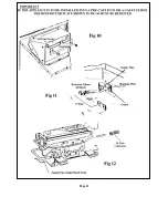
B. SERVICING COMPONENTS BELOW THE BURNER ASSEMBLY: Remove Glass front and fender,
coals, coal supports, burner inserts and front simulated coal. To gain access to components below the burner
assembly it has to be removed from the case by disconnecting the gas supply at the inlet elbow and unscrewing the
two screws at the base of the fascia panel.

i) TO CLEAN OR REPLACE THE INJECTOR: Unscrew the compression nut connecting the gas supply to the
elbow injector while supporting the injector to prevent distortion of the framework. Unscrew and remove the gas
supply tube from the gas control valve, hold the injector lock nut with a spanner and rotate the injector.  Replace in
reverse order.

ii) TO REPLACE THE GAS CONTROL (Tap/FSD): Disconnect the three gas pipes and the thermocouple from
the control.  Pull off the knob and lay to one side.  Undo the retaining nut at the front of the tap niting assembly to
withdraw control from the mounting bracket.  Replace in reverse order.

iii) TO REPLACE THE PIEZO IGNITER: Pull off the HT lead from the rear of the igniter.  Retain the metal
fixing nut with one finger and rotate the body of the igniter to unscrew.  Withdraw the igniter from the front. 
Replace in reverse order and reconnect the HT lead.

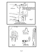
iv) OXY/PILOT ASSEMBLY: The assembly is not a serviceable item as part of its calibration depends upon the
proximity of the spark electrode and thermocouple tip. The assembly can be replaced by removing the tube nut and
tube from the base of the pilot and the thermocouple from the FFD also the igniter lead and the two M4 screws
securing the bracket to the framework. Replace in the reverse order. The spark gap is shown in fig 18.

Page 14

Содержание U19019 G20

Страница 1: ...81139 Issue 3 52 7 1 0 USERS INSTRUCTIONS THIS CAT I2H APPLIANCE IS FOR USE ON NATURAL GAS G20 AT A SUPPLY PRESSURE OF 20 mbar GB and IE HAND THESE INSTRUCTIONS TO THE USER ...

Страница 2: ...TED WITH SPECIAL HEAT RESISTING GLASS PANELS IF ANY PANEL IS DAMAGED THE FIRE MUST NOT BE USED AND A REPLACEMENT SPARE PANEL MUST BE OBTAINED TO CARRY OUT THE REPAIR It is very important that the warm air outlet grilles are not obstructed or used for drying towels etc When the fire is new an initial odour may be detected This is due to certain materials used during the manufacture of the fibre com...

Страница 3: ...ntrol and check that the pilot flame remains lit Refer to Fig 3 to view pilot Note For convenience the unit can be operated with the pilot only e g with the control knob set in the IGN position Push in the gas control slightly and turn anticlockwise so that the indicator dot is at the required setting Replace the Fret controls cover To turn off the appliance and pilot turn the gas control clockwis...

Страница 4: ...rom your face so that you avoid inhaling the dust We do not recommend the use of a normal domestic vacuum cleaner which may blow dust back into the air Care fully lift off the coals and the coal support shelf remove the L R hand side cheeks also the simulated coal front lift out the two burner inserts if necessary remove the back panel Any debris in the burner ports may be removed with a thin piec...

Страница 5: ...otch at the rear Lay a further row of four coals behind the front row with stepped corners in the rear corners of the front row the two centre coals having notches in the rear top corners Lay two more coals in the notches of the centre two coals See Fig 5 Lay the three small coals on the top L R corners and in the centre of the back row Page 5 ...

Страница 6: ...E APPLIANCE AND CLEANING THE WINDOW The fire must be turned off and allowed to cool for approximately 2 hours The paintwork should be cleaned with a soft cloth or soapy water The brass trim can be cleaned with most proprietary brands of metal cleaners although care must be taken not to use abrasive materials The glass window can be cleaned with most proprietary window cleaners To clean the coal be...

Страница 7: ...________________________________ and Address __________________________________________________ __________________________________________________ Date of Purchase __________________________________________________ Serial Number __________________________________________________ MAX HEAT INPUT 5 42kW 18500 Btu h Gross Royal Cozyfires are manufactured by CROSSLEE plc Aber Park Industrial Estate Abe...

Страница 8: ...81140 Issue 3 52 7 1 0 INSTALLATION AND SERVICING INSTRUCTIONS THIS CAT I2H APPLIANCE IS FOR USE ON NATURAL GAS G20 AT A SUPPLY PRESSURE OF 20 mbar GB and IE HAND THESE INSTRUCTIONS TO THE USER ...

Страница 9: ...e to the appliance Clearances required for combustible shelves are shown on page 4 This product uses fuel effect pieces gaskets and insulation material containing Refractory Ceramic Fibre RCF which are man made vitreous silicate fibres Excessive exposure to these materials may cause temporary irritation to eyes skin and respiratory tract consequently it makes sense to take care when handling these...

Страница 10: ...e is available the chairbrick will have to be removed b A twin walled metal flue box manufactured to BS 715 with a 125mm diameter insulated flue with a minimum effective height of 3 metres See page 6 c A pre cast flue conforming to the requirements of BS 1289 Pt 1 1986 including properly constructed pre cast flues formerly BS 1289 1975 with a cross sectional area of 13000sq mm Dampers register pla...

Страница 11: ...equired to any combustible material to the side of the appliance must be 150mm Clearance to shelves Minimum clearances to undersides of a 150mm deep combustible shelf from the hearth must be 830mm Add 12 5mm to this clearance for every 25mm increase in depth of shelf ...

Страница 12: ...Page 5 ...

Страница 13: ...d be enveloped with insulation material such as rockwool or similar to prevent a build up of heat within the structure An air gap of 75mm should be maintained between any combustible materials and any part of the flue box or 25mm of insulation between the flue box and the combustible material It is important that both the back panel and the appliance are sealed to the gas flue to prevent any leaka...

Страница 14: ...891 1988 dealing with enclosed pipes The Standard requires that when a gas pipe is fed through a wall the pipe should be enclosed in a tight sleeve to protect against failure caused by movement and shall be constructed to prevent passage of gas either between the pipe and sleeve or sleeve and wall DISMANTLING THE APPLIANCE PRIOR TO INSTALLATION Carefully remove the front glass panel held in positi...

Страница 15: ... coil the excess to ensure sufficient length of wire is available so the appliance can be removed for servicing or debris removal b ii With spacer frame fitted The spacer frame must be fitted to the rear of the appliance which will require either the removal of the screws and captive nuts from the fixing holes in the frame of the appliance or the knock out blanks semi sheared holes Assemble to the...

Страница 16: ...Page 8 ...

Страница 17: ...Page 9 ...

Страница 18: ...Page 10 ...

Страница 19: ...Page 11 ...

Страница 20: ...Page 12 ...

Страница 21: ...here is still any evidence of spillage then there is a fault with the chimney Disconnect the fire and seek advice from an expert Position the wrap around fender with the L R hand ends located in the slots in the side covers and secure at the front with two screws viewed through the front aperture tighten the top two screws of the side covers Slide the canopy down over the top of the appliance with...

Страница 22: ...ot classified as hazardous waste and may be disposed of at a tipping site licensed for the disposal of industrial waste Protective clothing is not required when handling these articles but we recommend you follow the normal hygiene rules of not smoking eating or drinking in the work area and always wash your hands before eating or drinking Any sooty deposit on the thermocouple probe can be cleaned...

Страница 23: ...Page 15 ...

Страница 24: ... s Name and Address Supplier s Name and address Installer s Name and Address Date of Purchase Serial Number Please return this section with any components that are faulty under guarantee MAX HEAT INPUT 5 42kW 18500 Btu h Gross Royal Cozyfires are manufactured by CROSSLEE plc Aber Park Industrial Estate Aber Road Flint Flintshire CH6 5EX Spares Tel 01422 203963 Fax 01422 204475 Service GSA Ltd 0170...

Отзывы: