background image

PRINCIPLE OF OPERATION
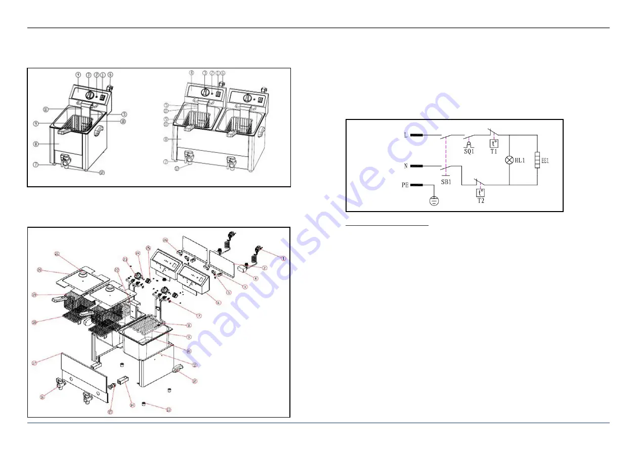
Assembly

1. ON-OFF-Switch 2. Control Light 3. Thermostat Knob 4. Electric Box 5. Heating Element 6. Power Cable 
7. Rubber Foot 8. Housing 9. Frying Basket 10. Tank 11. Protection Board 12. Drain Valve

EN

EN

Solid Diagram

1. Power Cable 2. Cover of the Electric Box 3. Connector 4. Relay 5. Microswitch 6. Electric Box
7. Hanging 8. Temperature Sensor 9. Heating Element 10. Tank 11. Housing 12. Plastic Handle
13. Rubber Foot 14. Square Tube 15. Connector lug 16. Drain Valve 17. Front Plate 19. Frying Basket
20. Cover 21. Handle of the Cover 22. Protection  23. Thermostat Knob 24. Control Light
25. ON/OFF-Switch 26. Temperature limiter

Wiring Diagram

230 V / 50 Hz

The device is composed of:
1.  An ON/OFF switch, 
2.  A thermostat to regulate the temperature at the level wished, 
3.  A control light (orange for the heating), 
4.  A  heating  element  in  the  lower  part  of  the  device,  which  is  controlled  by  the 

thermostat. 

FUNCTIONING 

The temperature measurement in the tank is made at regular intervals. This information 
is transmitted to the thermostat as a current value, and gets compared to the value 
set by the user. 

• 

If the current value is inferior to the set value, the thermostat makes the device 
heat. 

• 

If the current value is superior or equal to the set value, the thermostat stops the 
heating. 

4

Rev. 02.03.2021

5

Rev. 02.03.2021

Содержание RC-CEF 13E-EGO

Страница 1: ...expondo de USER MANUAL FRYER RC CEF 13E EGO EL UK ...

Страница 2: ...ployees how to use the device properly Make sure the hot air can circulate well and place the device more than10cm away from walls and other electrical devices Aerate well the working area Do not place the device close to combustible materials It may happen that by first use the heating element produces a light smoke This is absolutely normal Simply check that the smoke can evaporate and that a go...

Страница 3: ...3 Thermostat Knob 24 Control Light 25 ON OFF Switch 26 Temperature limiter Wiring Diagram 230V 50 Hz The device is composed of 1 An ON OFF switch 2 A thermostat to regulate the temperature at the level wished 3 A control light orange for the heating 4 A heating element in the lower part of the device which is controlled by the thermostat FUNCTIONING The temperature measurement in the tank is made ...

Страница 4: ...h which you can earth the fryer To do so please use a copper cable of min 2mm Basket assembly Please check you mounted the basket and its handle right so that the basket remains stable while working OPERATION 1 Plug in the device 2 Fill the tank with liquid oil so that the oil level is between the two marks on the side of the tank Never use the device without oil 3 Turn on the device The ON OFF kn...

Страница 5: ...ollowing information Invoice number and serial number the latest is to be found on the technical plate on the device If relevant a picture of the damaged broken or defective part It will be easier for your customer service clerk to determinate the source of the problem if you make a detailed and precise description of the matter Avoid formulations like the device doesn t heat which may mean that i...

Страница 6: ...ting The thermal fuse is released too early Press the reset knob on the back side of the device Exchange the reset knob Check if the thermostat works properly The fryer doesn t stop heating The thermostat is defect 2 The thermal fuse is defect Exchange the thermostat Exchange the thermal fuse EN 10 Rev 02 03 2021 11 Rev 02 03 2021 NOTES NOTZIEN ...

Страница 7: ...nden Möglichkeiten der Rückgabe oder Sammlung von Altgeräten 1 RICHTLINIE 2002 96 EG DES EUROPÄISCHEN PARLAMENTS UND DES RATES ÜBER ELEKTRO UND ELEKTRONIK ALTGERÄTE 2 Gesetz über das Inverkehrbringen die Rücknahme und die umweltverträgliche Entsorgung von Elektro und Elektronikgeräten Elektro und Elektronikgerätegesetz ElektroG Umwelt und Entsorgungshinweise Utylizacja produktu Produkty elektryczn...

Отзывы: