10
The port will be assigned automatically such as COM3. This is indicated by the red box in the screen shot
above. This is the COM port that the users should use to connect to the HASCP.
3.1.c
Step 3
: HASCP Interconnecting
Connect the keyed green five-pin connector on the instrument cable pig-tail to the USB-Serial adaptor
Insert the USB connector into a USB port on the PC
3.1.d
Step 4
. Connecting to the Instrument via Software
Once all of the instrument interconnections have taken place, (presented in Step 3) open the RTI HASCP
Software to communicate with the ADCP.
3.2
Communications
i.
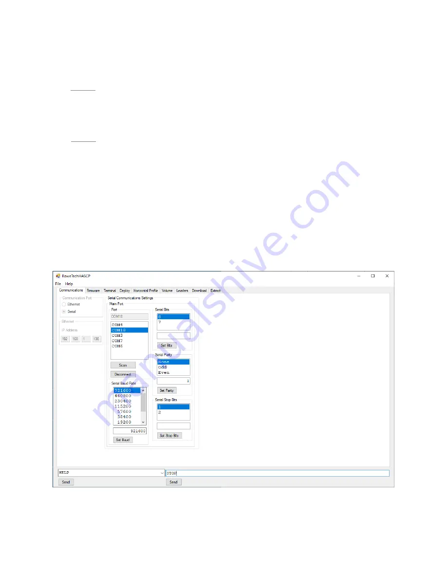
Click the Communications TAB on the top left of the software window. Refer to Figure
4.
ii.
If the HASCP is connected and outputting data, the text page on the right will show what
data in being transferred. If not, the text page will be blank.
iii.
To change the port settings:
1.
Select the communications port which is connected to the HASCP.
2.
Select Baud Rate, number of Bits, Parity, and Stop Bits.
Figure 4. Connecting to HASCP – Communications set up.
Содержание HASCP
Страница 26: ...26 Figure 15 Firmware Tab in the RTI HASCP software...
Страница 68: ...68 8 Cable Wiring Diagrams This section outlines the HASCP communication cable wiring...
Страница 73: ...73 10 Mechanical Drawings and Assembly Figure 23 Outline drawing of the HASCP unit MCBH 10M...
Страница 74: ...74 Figure 24 Location of transducer beams in the HASCP unit...
Страница 76: ...76 Figure 26 Exploded view of the HASCP unit showing the details of the hardware used...
Страница 78: ...78 Figure 28 HASCP mounted on a pole used for internal testing at RTI...


