background image

- 8 -

E4L

E4

H

L

H

L

RC210

90

68

120

68

RC220-RC265

90

110

120

110

RC270-RC280, 

RC88

100

160

130

160

RCG90-RCG100 155*

200*

185*

200*

Tabell 14pt bold 

Bold på rubriker uppe, allt under ska vara regular.

Allt utom spalten med RC-förteckningar ska vara 

centrerat i våg och lodrätt. RC-spalten ska vara 

vänsterlagd.

Strl på texten varierar beroende på utrymme men 

10pt är standard

www.rotork.com  www.remotecontrol.se

5

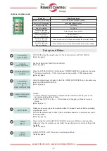
INPUT is at 4-20mA 0-10V or 0-5V when change

DIP SWITCH setting to change to fit the table

1. DIP SWITCH Change

INPUT

1

2

3

4-20mA

ON

OFF

OFF

2 - 10V

OFF

ON

OFF

0 - 5V

OFF

OFF

ON

0 - 10V

OFF

ON

ON

1 - 5V

OFF

OFF

OFF

2. Optional Modulation

DIP SWITCH No.4 Button ON

3. 0V input, Push the ZERO BUTTON

ACTUATOR CLOSE

4. After the 5V or 10V input, SPAN BUTTON push

ACTUATOR OPEN

5.

DIP SWITCH No.4 Button OFF

6. 0-10V or 0-5V input, to verify that the normal operation.

6

INPUT 4-20mA (0-10V) or 0-5V and 6-18mA (1-9V)

If you want to change a current signal

1. Optional Modulation

DIP SWITCH No.4 Button ON

2. 6mA input, Push the ZERO BUTTON

ACTUATOR CLOSE

4. After the 18mA input, SPAN BUTTON push

ACTUATOR OPEN

5.

DIP SWITCH No.4 Button OFF

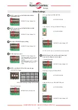
Other Settings

1

INPUT in case of error, ACTUATOR FULL OPEN 

automatically when

DIP SWITCH No.1 Button ON

2

INPUT in case of error, ACTUATOR FULL CLOSE 

automatically when

DIP SWITCH No.2 Button ON

3

When the ACTUATOR reverse setting

DIP SWITCH No.6 Button ON

4

A FULL function is used

DIP SWITCH No.3 Button ON

If the input signal is at 3.8~4.3mA, 

the ACTUATOR turns to a FULL 

CLOSE.

If the input signal is at 19.7~20.2mA, 

the ACTUATOR turns to a FULL 

OPEN.

Содержание RCEL SA

Страница 1: ...scale 0 5 Output Signal 4 20mA DC Load Resistance 750 Wiring Terminals YW 396 2P 3EA 3P 5P connector Visual Indicators 4 LEDS Power Blue Fault Yellow Open Red Close Green Calibration Method ASCN Auto...

Страница 2: ...Specification PCU Board A PCU Board B AC INPUT SIGNAL SELECTION AUTOSCAN SPAN ZERO TIME DELAY DEAD BAND 4 20mA DC OUTPUT SIGNAL 4 20mA DC INPUT SIGNAL OUTPUT SIGNAL CONNECTION OPEN AUTO CLOSE AC POWER...

Страница 3: ...CU Board A PCU Board B DC INPUT SIGNAL SELECTION AUTOSCAN SPAN ZERO TIME DELAY DEAD BAND 4 20mA DC OUTPUT SIGNAL 4 20mA DC INPUT SIGNAL OUTPUT SIGNAL CONNECTION CCW CW OLS CLS OPEN CLOSE AUTO POWER PO...

Страница 4: ...button SPAN Open manual control button Input module button ASCN AUTO SCAN BUTTON ACTUATOR automatic control button delivered from the factory the resistance value of potentiometer may can be changed i...

Страница 5: ...mine the value The factory is set to 80 120 If you have not been set 80 120 please reset Refer to page 6 3 POTENTIOMETER CHECK Using the manual lever or handle to the FULL OPEN ACTUATOR then in the sa...

Страница 6: ...irection to actuate the open switches AOLS OLS ACLS CLS POTENTIOMETER Setting Actuator delivered full close at 80 120 After limit setting it should check at closed 80 120 Make actuator full closed and...

Страница 7: ...plug provided with the ACTUATOR Do not remove the remaining plug as it is already sealed Main Power must only be applied when the top cover is re installed on the actuator body If the main power is on...

Страница 8: ...mA 0 10V or 0 5V and 6 18mA 1 9V If you want to change a current signal 1 Optional Modulation DIP SWITCH No 4 Button ON 2 6mA input Push the ZERO BUTTON ACTUATOR CLOSE 4 After the 18mA input SPAN BUTT...

Страница 9: ...Limit Power input Wage terminal No 2 No 5 Jump ACTUATOR automatic close open AUTO Button push 25sec Check the resistent value of PIU The resistant value when closed 80 120 4mA Close 20mA Open 4 20mA...

Страница 10: ...isengaged Check frequency of operation or JAMMED gears Wiring failure Confirm unit is properly wired per wiring diagram Main board failure Replace main board LED lights not operating LED board failure...

Отзывы: