CK
a
& CK
ra
Atronik Start Up Guide
8
Test Feedback Switches
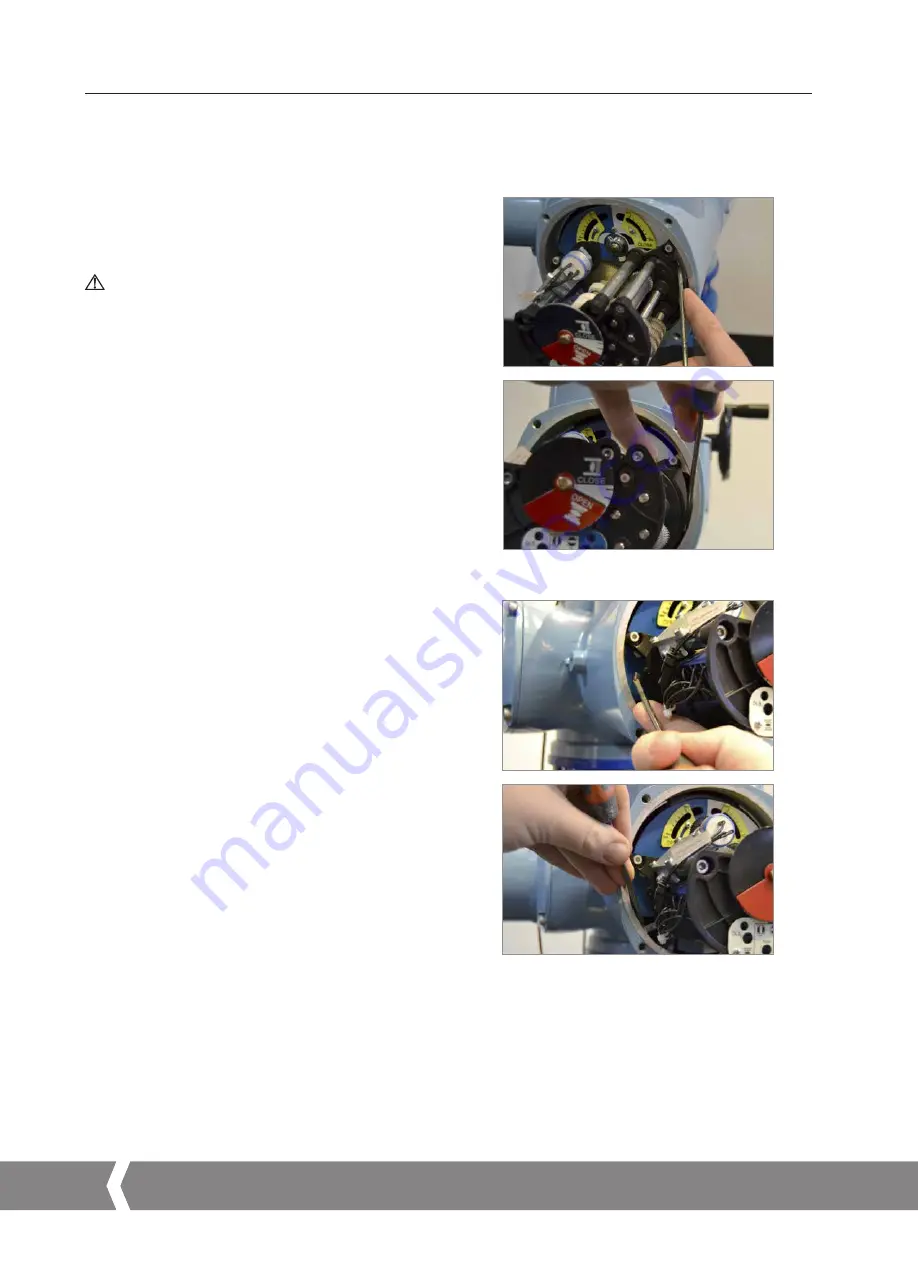
3) Test torque switches in both directions using the TS TEST
lever shown on the left side of the unit between the AID
module and Mechanical Switch Mechanism (move DOWN
for open, UP for close).
Torque switch status is shown via the fault indicator. Fault
should illuminate when the torque switch is engaged in
either direction.
3.2 Additional Indication Drive
The Additional Indication Drive (AID) supplements the
mechanical switch mechanism to increase functionality.
Test Feedback Switches
1) Confirm the torque or limit switches are functional by
monitoring feedback on the Atronik status indicators
during switch testing.
The main power supply must be maintained
during this test procedure to ensure feedback
via the Atronik.
It is not possible to test a switch that is already actuated by
the mechanism (for instance, at the end of travel limits). To
ensure that all switches can be tested correctly, move the
actuator to a mid-travel position and confirm that none of
the switches are active before beginning the test procedure.
2) Test position switches in both directions using the LS TEST
lever shown on the right side of the unit between the AID
module and Mechanical Switch Mechanism (move DOWN
for open, UP for close).
The applicable status indicator will illuminate when the
switch is active. Verify that mid-travel is illuminated prior to
testing the switch status.
3. Commissioning
A4
US
US
A4
US
A4
US
A4
A4
US
US
A4
US
A4
A4
US


