3
x
Installation
22
FA ROTEX Solaris RPS3 25M - 03/2010
3.9
Connecting several DHW storage tanks together
To ensure an appropriate storage tank volume on large-scale Solaris systems, it is necessary to connect several hot water storage
tanks in parallel.
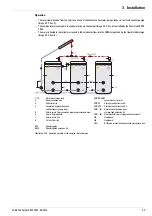
It is possible to connect a maximum of 3 hot water storage tanks to form a storage battery with the ROTEX tank extension kits.
With the Solaris CON SX (
16 01 07
) tank extension kit, 2 hot water storage tanks which can be used with Solaris systems
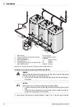
can be connected (Image 3-32). Solaris tank extension kit 2 CON SXE (
16 01 11
) for a 3rd hot water storage tank.
In addition to the prefabricated flow manifolds, these kits also contain the return connection lines (Image 3-32). For such a
storage battery, a CON RA 25M (
16 01 13
) connection set is required to connect the pump to the first hot water storage
tank.
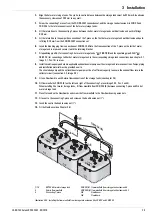
If a greater number of hot water storage tanks is to be connected, the flow manifold must be provided on-site as shown in
Image 3-33.
The ROTEX FlowGuard FLG (
1
6 41 02
) ensures even filling of the connected hot water storage tanks. One FlowGuard must
be installed for each hot water storage tank. The FlowSensor is installed in the common flow pipe (Image 3-32).
To establish the return connection, one CON RA 25M (
16 01 13
) connection set is required per hot water storage tank.
Additional equalising pipes must be connected to all hot water storage tanks connected in one Solaris system (equalising pipe
AGL for connecting 2 hot water storage tanks (
16 01 08
), equalising pipe extension kit AGLE for each further hot water
storage tank (
16 01 12
).
As the flow rate of the water circulating in the solar system during intake and discharge can be different despite balancing via
the FlowGuard throttle valves (FLG) in the hot water storage tanks (Image 3-32, difference in level "
∆
H"), it is possible for one
of the hot water storage tanks to "overflow" if there is no equalising pipe fitted. Installing an equalising pipe prevents an
excessive rise in the fluid level in one of the hot water storage tanks.
It is possible to combine several "storage batteries" for large installations (see also the schematic diagrams for large installations
in Chapter 7 "Hydraulic system integration").
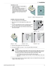
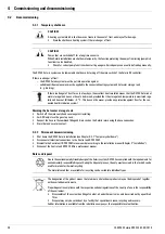
7.
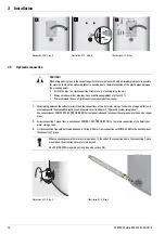
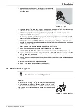
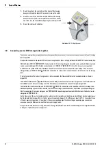
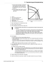
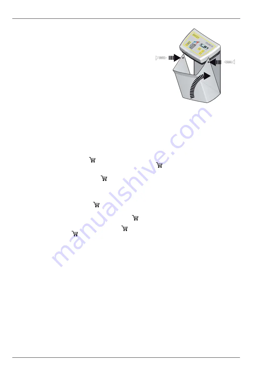
Route the cable of the controller at the bottom of the housing
baseplate through the labyrinth to prevent strain on the cable.
8.
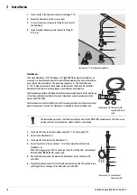
Hook the cover of the Control unit RPS3 25M into the housing
baseplate at the bottom, fold it upwards towards the controller
and screw it to the controller housing using the screws provided.
9.
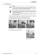
Attach the cable with cable ties.
Illustration 3-31 Fitting the cover
1
2
2

