10
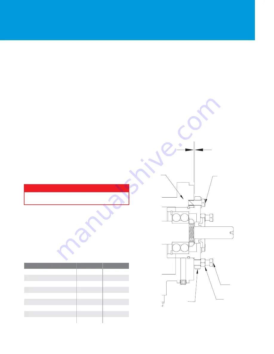
FEELER GAUGE TECHNIQUE
1. Lock out power to the pump driver.
2. Remove the coupling guard.
3. Loosen jacking bolts (370D) and jam nuts (423).
4. Tighten bearing housing bolts (370C) evenly, while
slowly rotating the shaft until the impeller starts to rub on
the casing (100).
5. Using a feeler gauge, set the gap between the 3 hous-
ing bolts (370C) and the bearing housing (134). (Refer to
Table 6 for settings.)
6. Tighten jack bolts (370D) evenly until bearing housing
backs out and contacts the bearing housing bolts (370C).
7. Tighten jam nuts (423) evenly, rotating the shaft to
make sure the assembly turns freely.
8. Reinstall the coupling guard.
9. Unlock power to the pump driver.
Fig. 7
Storage, Assembly & Disassembly of Mechanical
Seal:
Read, understand & follow the manufacture’s installa-
tion, operation and maintenance instructions.
Type 1: Installation of Mechanical Seal:
1. MTR, LTR, XLR Slide the stuffing box cover over the
shaft/sleeve. Bolt the cover (184) to the frame adapt-
er(108). STR Slide the 6" or 8" stuffing box cover (184) with
adapter ring (108) over shaft and bolt to bearing.
2. Mark / scribe the shaft at the face of the stuffing box.
3. Unbolt and remove the stuffing box cover.
4. Locate the installation reference dimension on the seal
installation drawing. Normally this is the dimension from
the face of the stuffing box to the rear of the seal.
5. Mark the shaft with a felt marker or marking tool at the
dimension (i.e. 1/32").
6. Lubricate the shaft with silicon grease or soapy water.
Slide the seal onto the shaft. Line up the face of the seal
with your mark and secure with set screw.
7. Reassemble the pump.
IMPELLER CLEARANCE
Over time a change in pump performance may be
noticed. Performance can usually be renewed by reset-
ting the impeller clearance.
Impeller Clearance Setting
A gradual loss in head &/or capacity can occur. You may
restore performance by adjusting the impeller clearance,
which is the measurement between the impeller vanes
and the surface of the casing.
Lock out motor power to prevent accidental startup
and physical injury.
! WARNING !
Pumpage Temperature
STR
MTR / LTR
0.005 (.13)
0.005 (.13)
0.005 (.13)
0.006 (.16)
0.007 (.18)
0.008 (.21)
0.009 (.23)
0.011 (.28)
0.013 (.33)
.008 (.20)
.008 (.20)
.008 (.20)
.099 (.23)
.010 (.26)
.011 (.28)
.012 (.30)
.014 (.36)
.016 (.41)
-20 to 150° F (-29-66° C)
Up to 175° F (80° C)
Up to 200° F (93° C)
Up to 225° F (107° C)
Up to 250° F (121° C)
Up to 275° F (135° C)
Up to 300° F (149° C)
Up to 350° F (177° C)
Up to 400° F (204° C)
134
423
370D
228
370C
Содержание ANSI LTR
Страница 1: ...ANSI Pump Series INSTALLATION OPERATION MAINTENANCE MANUAL...
Страница 27: ...23 STR SECTIONAL VIEW 1196 100 101 126 184 108 122 112A 496 332A 134 136 319 168A 333A 250 186 351 412A...
Страница 33: ...29 STR SECTIONAL VIEW 1196LF 100 101 126 184 108 122 112A 496 332A 134 136 319 168A 333A 185 186 351 412A 107...


