12.
Commissioning
30
117592
●
03/2013
12. Commissioning
Carry out a “safety inspection“ before
commissioning.
If a competent person (factory-trained fitter) installs
the lift, this person also carries out the safety
inspection.
If the operator installs the lift, a competent person
must be assigned to carry out the safety inspection.
The competent person completes the forms
“Installation Report“ and “Initial safety inspection
before commissioning“ and verifies that the lift is
fully functional. The lift is now approved for use.
The installation report must be sent to the
manufacturer after commissioning.
The installation and commissioning of
electrical and hydraulic equipment, safety
system and accessories are described in the
following sections. Follow the correct
sequence to guarantee that the lift can be
operated correctly, in order that the safety of
people is not at risk.
CAUTION
Follow the instructions
Any damage caused through non-compliance
with the instructions below cannot be
attributed to the manufacturer; in such a case,
the manufacturer shall assume no liability. The
warranty shall also be deemed null and void.
a) Electrical circuit
If the hydraulic unit is connected to the power
supply and the main switch is set to “1“ the
control unit is activated.
Press the "Up" button for several seconds and
check that the motor is turning properly.
If there is no build up of pressure and the slider
block does not move, then alter the direction of
rotation of the motor by inverting the phases of
the power cable.
Carry out another check.
Check all functions of the controls and ensure
that they react in accordance to the symbols.
b) Hydraulic circuit
Proceed as follows to commission the hydraulic
circuit:
Set the main switch to “1“ to supply power to the
control unit.
Raise and lower several times without load up to
the end limits.
Ensure that the hydraulic system fittings are
properly sealed.
Check the hydraulic oil level in the tank when
the slider block is in the bottom position.
Check that the hydraulic lines are correctly
positioned and that they do not chafe against
stationary parts.
c) Adjust the calibration pressure of the
hydraulic circuit
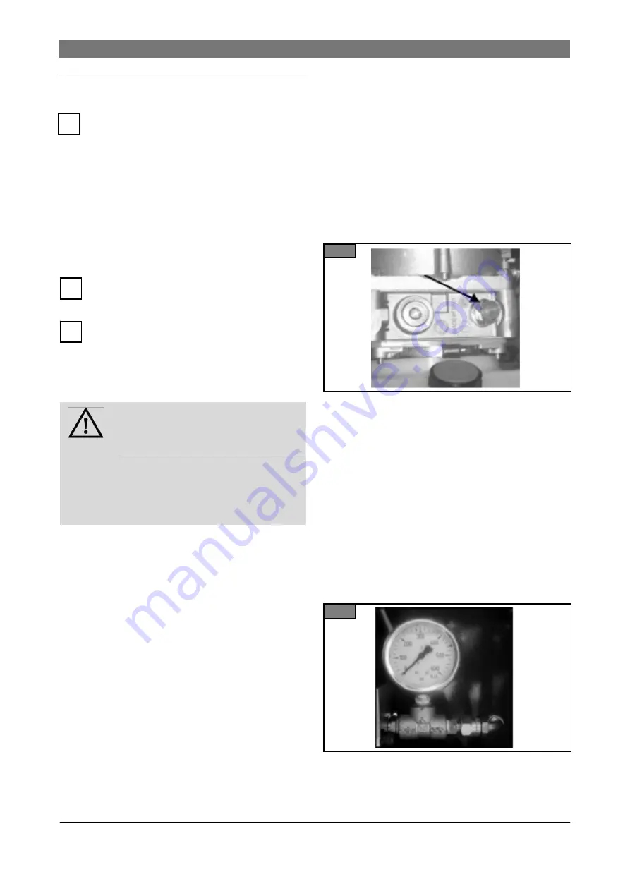
Install a manometer (Fig. 29) on the fitting
provided for the pressure gauge.
28
Press the "Up" button to raise the slider block to
the mechanical stop at full rise.
Keep the button pressed for a further few
seconds after the slider block has touched the
stop at full rise and read the pressure off the
manometer.
If this pressure does not correspond to the
calibration pressure of the hydraulic circuit as
specified under “TECHNICAL DATA“ use the
adjustment screw (Fig. 28, arrow) on the
pressure release valve behind the lock nut to
adjust it.
Fit a plastic cap (orange) to the lock nut to lock
the pressure release valve.
29
d) Broken chain control (lifting chains)
Each slider block is fitted with a chain:
i
i
i
Содержание SGL35
Страница 2: ......
Страница 4: ......
Страница 44: ...Diagrams spare parts lists 40 117592 03 2013 Figure 1 ...
Страница 45: ...Figure 2 ...
Страница 46: ...Diagrams spare parts lists 42 117592 03 2013 Figure 3 Figure 4 ...
Страница 47: ...Figure 5 Figure 7 Figure 6 ...
Страница 48: ...Diagrams spare parts lists 44 117592 03 2013 Figure 8 ...
Страница 49: ...Figure 9 ...
Страница 52: ...Diagrams spare parts lists 48 117592 03 2013 ...


