background image

55

2

Hardware Installation

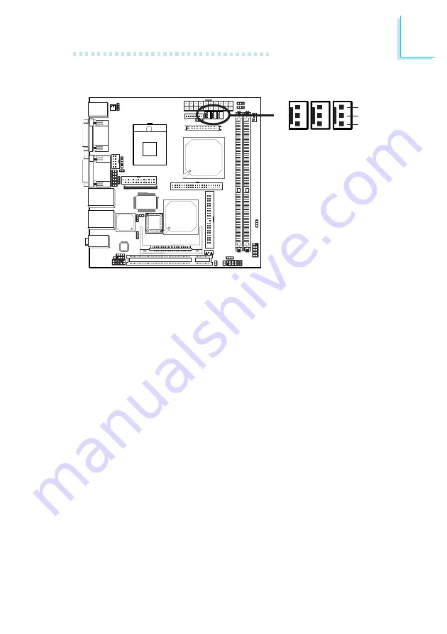
Cooling Fan Connectors

Connect the CPU fan’s cable connector to the CPU fan connector
(J15) on the system board. The chassis fan (J17) and 2nd fan (J18)
connectors are used to connect an additional cooling fan. The cooling
fans will provide adequate airflow throughout the chassis to prevent
overheating the CPU and system board components.

BIOS Setting

The “PC Health Status” submenu of the BIOS will display the current
speed of the cooling fans. Refer to chapter 3 for more information.

X

CPU

fan

Sense

1 2 V

Ground

1

3

Chassis

fan

2nd

fan

Содержание G5M150-N

Страница 1: ...G5M150 N System Board User s Manual 935 G5M152 000 A84300446...

Страница 2: ...eserves the right to revise this publication and make changes to its contents at any time without obligation to notify any person or entity of such revisions or changes 2005 All Rights Reserved Tradem...

Страница 3: ...ticular installation If this equipment does cause harmful interference to radio or television reception which can be determined by turning the equipment off and on the user is encouraged to try to cor...

Страница 4: ...lectronic file of this manual is included in the CD To view the user s manual in the CD insert the CD into a CD ROM drive The autorun screen Main Board Utility CD will appear Click User s Manual on th...

Страница 5: ...stallation 2 1 System Board Layout 2 2 System Memory 2 3 CPU 2 4 Jumper Settings 2 5 Rear Panel I O Ports 2 6 I O Connectors Chapter 3 BIOS Setup 3 1 Award BIOS Setup Utility 3 5 Updating the BIOS Cha...

Страница 6: ...Introduction 1 6 Appendix A Watchdog Timer A 1 Watchdog Timer Appendix B System Error Messages B 1 POST Beep B 2 Error Messages Appendix C Troubleshooting C 1 Troubleshooting Checklist 112 112 114 111...

Страница 7: ...or PC2700 DDR333 DDR SDRAM DIMM with ECC support Supports 128Mbit 256Mbit and 512Mbit technologies providing maximum capacity of 1GB with x16 devices and up to 2GB with high density 512Mbit technolog...

Страница 8: ...0MHz Render core frequency at 100 133 166 200 250MHz Intel Dual Frequency GraphicsTechnology 2D graphics engine Optimized 128 bit BLT engine 32 bit Alpha Blended cursor 8 bit 16 bit and 32 bit color 3...

Страница 9: ...ard Audio Features Realtek ALC202A 18 bit stereo full duplex codec with independent variable sampling rate High quality differential CD input True stereo line level outputs S PDIF out interface 2 chan...

Страница 10: ...or for LVDS LCD panel 1 connector for LCD Inverter power 1 front audio connector for line out and mic in jacks 1 CD in internal audio connector 1 S PDIF out connector 1 connector for IrDA interface 1...

Страница 11: ...herefore doubling the speed of data transfer S PDIF S PDIF is a standard audio file transfer format that transfers digital audio signals to a device without having to be converted first to an analog f...

Страница 12: ...oft Power Off mode to wake up power on to respond to calls coming from an external modem internal modem or respond to calls from a modem PCI card that uses the PCI PME Power Management Event signal to...

Страница 13: ...eet the ACPI Advanced Con figuration and Power Interface specification ACPI has energy saving features that enables PCs to implement Power Management and Plug and Play with operating systems that supp...

Страница 14: ...The system board is designed to protect the boot sector and partition table of your hard disk drive Package Checklist The system board package contains the following items The system board A user s m...

Страница 15: ...in S PDIF Front audio 1 LAN 2 select JP4 I O chip 1 Parallel 1 IDE 1 WOL Mini PCI AUX power J19 USB 5 6 USB 5 6 power JP9 1 IDE 2 1 FDD LCD Inverter power LCD power select JP6 LVDS LCD panel 1 CPU fa...

Страница 16: ...a metal part of the system chassis If a wrist strap is unavailable establish and maintain contact with the system chassis throughout any procedures requiring ESD protection The system board supports...

Страница 17: ...st correspond with Pin 1 of the socket 1 Pull the tabs which are at the ends of the socket to the side 2 Position the DIMM above the socket with the notch in the module aligned with the key on the soc...

Страница 18: ...vely designed for installing an Intel Pentium M Celeron M processor Installing the CPU 1 Make sure the PC and all other peripheral devices connected to it has been powered down 2 Disconnect all power...

Страница 19: ...touching the pins 6 Insert the CPU into the socket until it is seated in place The CPU will fit in only one orientation and can easily be inserted without exerting any force Use a screwdriver to turn...

Страница 20: ...y the fan and heat sink assembly included in the system board package The fan and heat sink package contains the fan and heat sink assembly and a retension module base CPU fan and heat sink assembly R...

Страница 21: ...important so that the fan heat sink will provide adequate cooling to the components of the system board Turn each Phillips head screw half way down first to initially stabilize the heat sink onto the...

Страница 22: ...When you install the CPU fan and heat sink assembly make sure the assembly is positioned in such a way that the direction of the airflow blows towards the north bridge This is to ensure optimum therm...

Страница 23: ...with the default values stored in the ROM BIOS To load the default values stored in the ROM BIOS please follow the steps below 1 Power off the system and unplug the power cord 2 Set JP5 pins 2 and 3 t...

Страница 24: ...PS 2 mouse to wake up the system BIOS Setting Configure the PS 2 keyboard mouse wake up function in the Integrated Peripherals submenu Super IO Device section of the BIOS Refer to chapter 3 for more i...

Страница 25: ...p From S3 in the Power Management Setup submenu of the BIOS must be set to Enabled Refer to chapter 3 for more information Important If you are using the Wake On USB Keyboard function for 2 USB ports...

Страница 26: ...26 2 Hardware Installation LCD Panel Power Select JP6 is used to select the power supplied to the LCD panel 1 2 On 5V 2 3 On 3 3V default X JP6 3 1 2 3 1 2...

Страница 27: ...27 2 Hardware Installation Inverter On Off Select 1 2 On Active Low 2 3 On Active High X JP10 3 1 2 3 1 2 JP10 is used to turn on or off the inverter s brightness...

Страница 28: ...connected to the LCD Brightness Control button of the LCD Display Panel It is used to adjust the brightness of the LCD Display Panel Increasing or decreasing the voltage to control the LCD panel s bri...

Страница 29: ...port requires auxiliary power from the system board set JP1 pins 9 11 and 10 12 to On This setting automatically sets COM 4 at RS 232 COM 4 RS232 RS485 AUX Select X JP1 1 2 11 12 JP1 1 3 2 4 7 9 8 10...

Страница 30: ...m to power on whenever AC power comes in set JP8 pins 1 and 2 to On If you want to use the power button set pins 2 and 3 to On Important If you want the system to automatically power on when power ret...

Страница 31: ...t AC in JP11 Off Power on via power button default JP11 is used to select the method of powering on the system Set JP11 to On if you want the system to automatically power on only the first time AC po...

Страница 32: ...requency has been locked by the manufacturer overclocking will have no effect Overclocking may result to the CPU s or system s instability and are not guaranteed to provide better system performance I...

Страница 33: ...lect the power supplied to the Mini PCI card that is installed in the Mini PCI socket Selecting 3VSB will allow you to use the wake up function supported by the Mini PCI card Mini PCI AUX Power X J19...

Страница 34: ...chip which controls the onboard LAN 1 port JP4 is used to enable or disable the onboard Intel 82551 LAN chip which controls the onboard LAN 2 port LAN Settings X JP4 3 1 2 3 1 2 1 2 On Enabled default...

Страница 35: ...tallation S1 is located at the solder side of the system board It is used to enable or disable the riser card Riser Card Select X S1 1 ON 2 3 4 5 6 1 ON 2 3 4 5 6 All On Riser card enabled All Off Ris...

Страница 36: ...r panel I O ports consist of the following PS 2 mouse port PS 2 keyboard port 3 COM ports VGA port 2 LAN ports 4 USB ports Mic in jack Line in jack Line out jack PS 2 K B COM 2 USB 3 4 USB 1 2 VGA Lin...

Страница 37: ...eserve IRQ12 for other expansion cards Warning Make sure to turn off your computer prior to connecting or disconnecting a mouse or keyboard Failure to do so may damage the system board Wake On PS 2 Ke...

Страница 38: ...figure the PS 2 wake up function in the Integrated Peripherals submenu Super IO Device section of the BIOS must be set accordingly Refer to chapter 3 for more information Important The 5VSB power sour...

Страница 39: ...that can be used with modems serial printers remote display terminals and other serial devices Jumper Setting If the serial device connected to COM 4 requires auxiliary power from the system board set...

Страница 40: ...pter or optional cable After you plug the monitor cable into the VGA port gently tighten the cable screws to hold the connector in place Some monitors have a switch that chooses between analog and TTL...

Страница 41: ...controlled by the Intel 82551QM chip is at location CN3 These ports allow the system board to connect to a local area network by means of a network hub Jumper Setting Use JP7 and JP4 to enable disable...

Страница 42: ...the system board The JUSB1 connector USB 5 6 allows you to connect 2 additional USB 2 0 1 1 ports The additional USB ports may be mounted on a card edge bracket Install the card edge bracket to the s...

Страница 43: ...board to wake up a system from the S3 STR Suspend To RAM state To use this function Jumper Setting JP2 and or JP9 must be set to 2 3 On 5VSB Refer to USB Power Select in this chapter for more informat...

Страница 44: ...in W Audio Jacks The system board is equipped with 3 audio jacks at location CN2 A jack is a one hole connecting interface for inserting a plug Mic in Jack Pink This jack is used to connect an externa...

Страница 45: ...ons Remove the jumper caps from pins 5 6 and pins 9 10 of J2 prior to connecting the front audio cable connector Make sure pin 1 of the cable connector is aligned with pin 1 of J2 If you are not using...

Страница 46: ...re Installation I O Connectors CD in Internal Audio Connector The CD in J4 connector is used to receive audio from a CD ROM drive TV tuner or MPEG card W 1 4 Right audio channel Left audio channel Gro...

Страница 47: ...ct an external S PDIF out port Your S PDIF out port may be mounted on a card edge bracket Install the card edge bracket to the system chassis then connect the audio cable connector to J3 Make sure pin...

Страница 48: ...onnectors transmit video signals and power from the system board to the LCD Display Panel Refer to the next page for the pin functions of these connectors Jumper Settings Refer to the Jumper Settings...

Страница 49: ...on GND LVDS_Out3 LVDS_Out3 GND LVDS_Out2 LVDS_Out2 GND LVDS_Out1 LVDS_Out1 GND LVDS_Out0 LVDS_Out0 GND LVDS_CLK1 LVDS_CLK1 GND COM3_DTR COM3_RTS COM3_RD COM3_CTS Pins 2 4 6 8 10 12 14 16 18 20 22 24 2...

Страница 50: ...es Port EPP Enhanced Parallel Port Function Allows normal speed operation but in one direction only Allows parallel port to operate in bidirectional mode and at a speed faster than the SPP s data tran...

Страница 51: ...ned above are optional Connecting the Floppy Disk Drive Cable Install one end of the floppy disk drive cable into the floppy disk connector J12 on the system board and the other end connector to the f...

Страница 52: ...1 connector is used for connecting 3 5 hard drives while the 44 pin IDE 2 connector is used for connecting 2 5 hard drives 2 0 pitch Each IDE connector supports 2 devices a Master and a Slave Use an I...

Страница 53: ...drives The system board supports Enhanced IDE or ATA 2 ATA 33 ATA 66 and ATA 100 hard drives We recommend that you use hard drives from the same manufacturer In a few cases drives from two different m...

Страница 54: ...le to the IrDA connector according to their pin functions BIOS Setting Set the Serial Port 1 Mode field in the Integrated Peripherals submenu Super IO Device section of the BIOS to the type of IrDA st...

Страница 55: ...ectors are used to connect an additional cooling fan The cooling fans will provide adequate airflow throughout the chassis to prevent overheating the CPU and system board components BIOS Setting The P...

Страница 56: ...he system board The network will detect Magic Packet and assert a wakeup signal to power up the system Refer to the add in card s manual for details Note Your LAN card must support the remote wake up...

Страница 57: ...use this function connect one end of the cable that came with the card to the card s wake on ring connector and the other end to location J1 on the system board If you are using an external modem the...

Страница 58: ...the chassis intrusion warning in the PC Health Status submenu of the BIOS Refer to chapter 3 for more information Hardware Monitor for Windows Install the Hardware Monitor for Windows utility By defau...

Страница 59: ...tant The system board consumes a minimal amount of power Due to its low power consumption you only need a 100W to 100W to 100W to 100W to 100W to 150W 150W 150W 150W 150W power supply Every power supp...

Страница 60: ...m PWR LED Power Standby LED When the system s power is on this LED will light When the system is in the S1 POS Power On Suspend state it will blink every second When the system is in the S3 STR Suspen...

Страница 61: ...61 2 Hardware Installation PCI Slot You can install a PCI expansion card or a customized riser card designed for 1 2 or 3 PCI slots expansion for low profile PCI card only into the PCI slot PCI Slot...

Страница 62: ...to install a Mini PCI card Mini PCI card is a small form factor PCI card with the same signal protocol electrical definitions and configuration definitions as the conventional PCI Jumper Setting To w...

Страница 63: ...r explains the Setup Utility for the Award BIOS After you power up the system the BIOS message appears on the screen and the memory count begins After the memory test the following message will appear...

Страница 64: ...is hour minute second The time is based on the 24 hour military time clock For example 1 p m is 13 00 00 Hour displays hours from 00 to 23 Minute displays minutes from 00 to 59 Second displays seconds...

Страница 65: ...e and show the IDE for the HDD CD ROM drive If a hard disk has not been installed select None Access Mode For hard drives larger than 528MB you would typically select the LBA type Certain operating sy...

Страница 66: ...ite timing Landing Zone This field displays the number of cylinders specified as the landing zone for the read write heads Sector This field displays the number sectors per track Drive A This field id...

Страница 67: ...d during power up The default setting is All Errors No Errors The system boot will not stop for any errors detected All Errors The system boot will stop whenever the BIOS detects a non fatal error All...

Страница 68: ...68 3 BIOS Setup Extended Memory Displays the amount of extended memory detected during boot up Total Memory Displays the total memory available in the system...

Страница 69: ...disk drive When this field is enabled the Award BIOS will monitor the boot sector and partition table of the hard disk drive If an attempt is made to write to the boot sector or partition table of th...

Страница 70: ...on the system When Enabled the BIOS will shorten or skip some check items during POST First Boot Device Second Boot Device Third Boot Device and Boot Other Device Select the drive to boot first second...

Страница 71: ...port for gate A20 Typematic Rate Setting Disabled Continually holding down a key on your keyboard will cause the BIOS to report that the key is down Enabled The BIOS will not only report that the key...

Страница 72: ...ystem will boot but access to Setup will be denied unless the correct password is entered at the prompt APIC Mode Leave this field in its default setting MPS Version Control for OS This field is used...

Страница 73: ...t the timing of the DRAM By SPD The EEPROM on a DIMM has SPD Serial Presence Detect data structure that stores information about the module such as the memory type memory size memory speed etc When th...

Страница 74: ...l memory clocks DRAM Data Integrity Mode The ECC Error Checking and Correction function is supported only in x72 72 bit PC SDRAM DIMMs If you are using x64 64 bit PC SDRAM DIMMs set this field to Non...

Страница 75: ...ry If more than 16MB of system memory is installed this field must be disabled to provide contiguous system memory Delayed Transaction When enabled this function frees up the PCI bus for other PCI mas...

Страница 76: ...he LCD flat panel display CRT LFP Select this option if you want the system to boot both the CRT and LCD flat panel display Panel Scaling This options are Auto On and Off Panel Number Panel 1 640x480...

Страница 77: ...n are for reference only Your version may not be identical to this one OnChip IDE Device Move the cursor to this field and press Enter The following screen will appear The settings on the screen are f...

Страница 78: ...will select the best available mode after checking your drive Auto The BIOS will automatically set the system according to your hard disk drive s timing Mode 0 4 You can select a mode that matches yo...

Страница 79: ...t be set to Enabled USB Keyboard Support If you are using a USB keyboard under DOS set this field to Enabled AC97 Audio Auto Select this option when using the onboard audio codec Disabled Select this...

Страница 80: ...ialize the onboard VGA or PCI first when the system boots Onboard AGP When the system boots it will first initialize the onboard VGA PCI Slot When the system boots it will first initialize PCI Watch D...

Страница 81: ...Key When this option is selected select the function key you would like to use to power on the system in the Hot Key Power On field Mouse Left When this option is selected double click the left button...

Страница 82: ...ystem Onboard FDC Controller Enabled Enables the onboard floppy disk controller Disabled Disables the onboard floppy disk controller Onboard Parallel Port 378 IRQ7 3BC IRQ7 278 IRQ5 Selects the I O ad...

Страница 83: ...s off when AC power failure occurs it will remain off when power returns If the system s power is on when AC power failure occurs the system will power on when power returns Onboard Serial Port 1 Onbo...

Страница 84: ...ems that support ACPI Currently only Windows 98 2000 ME XP supports this function If you want to use the Suspend to RAM function make sure this field is enabled then select S3 STR in the ACPI Suspend...

Страница 85: ...er Define Allows you to set the power saving time in the Suspend Mode field Video Off Method This determines the manner in which the monitor is blanked V H SYNC Blank This will cause the system to tur...

Страница 86: ...func tion is enabled or disabled if the power button is pushed and released in less than 4 sec the system enters the Suspend mode The purpose of this function is to prevent the system from powering o...

Страница 87: ...to calls coming from a modem Refer to Wake On Ring Connector in chapter 2 for more information Wake Up On LAN If you are using a LAN card that supports the remote wake up function set this field to En...

Страница 88: ...rk Disabled Disables the automatic power on function default Date of Month Alarm 0 The system will power on everyday according to the time set in the Time hh mm ss Alarm field 1 31 Select a date you w...

Страница 89: ...Data ESCD once automatically It will then recreate a new set of configuration data Disabled The BIOS will not reset the configuration data Resources Controlled By The Award Plug and Play BIOS has the...

Страница 90: ...GA Palette Snoop This field determines whether the MPEG ISA VESA VGA cards can work with PCI VGA or not The default value is Disabled Enabled MPEG ISA VESA VGA cards work with PCI VGA Disabled MPEG IS...

Страница 91: ...ll beep during a chassis intrusion event Current System Temp Current CPU Temperature Current Chassis Fan Speed Current CPU Fan Speed and Current 2nd Fan Speed These fields will show the internal tempe...

Страница 92: ...e only Your version may not be identical to this one Auto Detect PCI Clk When enabled the system will automatically send clock signals to existing PCI devices Spread Spectrum Leave this field in its d...

Страница 93: ...es permanently stored in the ROM chips These settings are not optimal and turn off all high performance features You should use these values only if you have hardware problems Highlight this option in...

Страница 94: ...Load Optimized Defaults option loads optimized settings from the BIOS ROM Use the default values as standard values for your system Highlight this option in the main menu and press Enter Type Y and p...

Страница 95: ...mpted for a password when you cold boot the system Use the arrow keys to highlight Set Supervisor Password and press Enter Type in the password You are limited to eight characters When done the messag...

Страница 96: ...only Set User Password that appears in the main menu screen Access to all other options is denied Use the arrow keys to highlight Set User Password and press Enter Type in the password You are limite...

Страница 97: ...ter Type Y and press Enter The modifications you have made will be written into the CMOS memory and the system will reboot You will once again see the initial diagnostics on the screen If you wish to...

Страница 98: ...ave made highlight Exit Without Saving and press Enter Type Y and press Enter The system will reboot and you will once again see the initial diagnostics on the screen If you wish to make any changes t...

Страница 99: ...enter the Award BIOS Setup Utility to set the first boot drive to Floppy 3 Save the setting and reboot the system 4 After the system booted from the floppy disk execute the flash utility by typing AW...

Страница 100: ...OS in your system We recommend that you save the current BIOS and its flash utility just in case you need to reinstall the BIOS To save the current BIOS press Y then enter the file name of the current...

Страница 101: ...equired to enhance the performance of the system board Insert the CD into a CD ROM drive The autorun screen Main Board Utility CD will appear If after inserting the CD Autorun did not automatically st...

Страница 102: ...s INF files so that the Intel chipset can be recognized and configured properly in the system To install the utility please follow the steps below 1 Click Intel Chipset Software Installation Utility...

Страница 103: ...rs To install the driver please follow the steps below 1 Click Audio Drivers on the main menu The following screen will appear 2 Follow the prompts on the screen to complete installation 3 Reboot the...

Страница 104: ...rs To install the driver please follow the steps below 1 Click Intel Graphics Drivers on the main menu The following screen will appear 2 Follow the prompts on the screen to complete installation 3 Re...

Страница 105: ...the USB 2 0 driver The drivers are supported in the following operating systems Windows 98 SE Windows ME and Windows 2000 To install the driver please follow the steps below 1 Click Intel USB 2 0 Driv...

Страница 106: ...SB 2 0 Drivers a readme screen will appear 2 Follow the installation instructions shown on the screen 3 Reboot the system for the driver to take effect Important If you are using Windows XP you must i...

Страница 107: ...oftware After installing the software run the application soft ware by double clicking the icon on the lower right of the taskbar The Intel R PROSet II screen will appear For more information about us...

Страница 108: ...ill pop up The utility can also be configured so that a beeping alarm will sound whenever an error occurs We recommend that you use the Default Setting which is the ideal setting that would keep the s...

Страница 109: ...se follow the steps below 1 Click Microsoft DirectX 9 Driver on the main menu The following screen will appear 2 Click I accept the agreement then click Next 3 Follow the prompts on the screen to comp...

Страница 110: ...tically start which is the Main Board Utility CD screen did not appear please go directly to the root directory of the CD and double click Setup 2 All steps or procedures to install software drivers a...

Страница 111: ...s to function it will also reset according to the time interval so that your system will continue to operate mov dx 02e Enter mov al 87 Enter out dx al Enter out dx al Enter mov dx 02e Enter mov al 07...

Страница 112: ...e consists of a single long beep B 2 Error Messages One or more of the following messages may be displayed if the BIOS detects an error during the POST This list indicates the error messages for all A...

Страница 113: ...e fixed disk Hard Disk s fail 08 Sector Verify failed Keyboard is locked out Unlock the key The BIOS detects that the keyboard is locked Keyboard controller is pulled low Keyboard error or no keyboard...

Страница 114: ...st the outlet by plugging in a lamp or other electrical device 4 The monitor is turned on 5 The display s brightness and contrast controls are adjusted properly 6 All add in boards in the expansion sl...

Страница 115: ...hing happens 1 Check that one end of the AC power cord is plugged into a live outlet and the other end properly plugged into the back of the system 2 Make sure that the voltage selection switch on the...

Страница 116: ...a cable connection problem However if your hard drive has a large capacity it will take a longer time to format Parallel Port The parallel printer doesn t respond when you try to print 1 Make sure tha...

Страница 117: ...onfigured correctly Keyboard Nothing happens when a key on the keyboard was pressed 1 Make sure the keyboard is properly connected 2 Make sure there are no objects resting on the keyboard and that no...

Отзывы: