Commissioning and operation
Version 2
RES-5008
Page 25
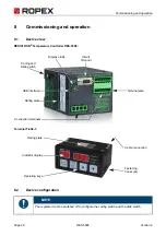
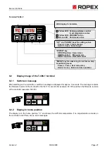
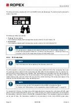
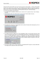
6. If the heating element is cold, please activate the function AUTOCAL at the Terminal T-408-1.
During the adjustment process (approx. 10...15 seconds) the “AC” display flashes in the T-408-1 terminal's
display.
The yellow “AUTOCAL” LED lights up for the duration of the calibration process. During this calibration process,
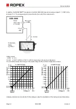
a voltage of approx. 0 VDC is output at the actual value output (terminals 17+7). A connected temperature
display ATR-x shows 0…3 °C.
After the zeroing has been carried out, the display of the T-408-1 terminal shows the home position again and
the “AUTOCAL” LED goes out. A voltage of 0.66 VDC (in 300 °C range and Autocal temperature = 20 °C) or
0.4 VDC (in 500 °C range) is reached at the actual value output. A connected Temperature display ATR-x must
be on the “Z” marking.
If the zeroing is unsuccessful, a corresponding error message is shown on the display of the T- 408-1 terminal
and the red “ALARM” LED blinks slowly (1 Hz). Then the configuration of the regulator is not correct
(
section 8.2 "Device configuration" on page 20, ROPEX application report). After the device configuration is
correct, perform zeroing again.
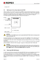
7. After successful zeroing, specify a defined temperature at the setpoint temperature and apply the START
signal (HEAT). The “SEALHEAT” LED on the Terminal T-408-1 and the “HEAT” LED at the regulator light up.
The actual temperature is shown on the display of the T-408-1 terminal. Thus, the heat-up and control proce-
dure can be observed:
The controller is functioning correctly if the temperature is constant, i.e., if it does not jump, oscillate or even
briefly goes in the wrong direction. Such action indicates an incorrect placement of the U
R
measurement line.
When an error message is issued, proceed according to section 9.25 "Error messages" on page 48.
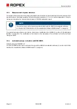
8. Burning in the heating element (
section 8.3 "Burning in and changing the heating element" on page 22) and
repeat AUTOCAL function.
8.4.2
Recommissioning after changing the heating element
While changing the heating element, proceed as per section 8.3 "Burning in and changing the heating element"
on page 22.
Continue with chap. 8.4.1 item 2 to item 8.
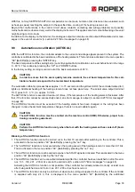
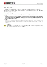
WARNING
Pay attention to correct alloys, dimensions and copper coating of the new heating element to
avoid malfunctions and overheating.

