background image

Ronk Vigilant

®

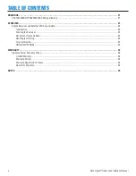
 Owner’s and Installation Manual


7

SAFETY

Safety Labels

Always replace any illegible or missing labels 
immediately. All safety labels must be legible to alert 
personnel to safety hazards. 

General Safety Precautions

!

 DANGER

DANGER! Equipment contains high voltage. 
Despite the safe design of the system, operating 
this equipment imprudently, neglecting its 
maintenance or being careless can result in 
death or serious injury.

!

 WARNING

The safety messages that follow have WARNING 
level hazards.

• 

Unauthorized or improper installation, operation, application 
or repair of this equipment is extremely dangerous.

• 

Only qualified electricians should attempt installation of this 
equipment, which must strictly comply with all applicable 
codes, standards and regulations.

• 

When connecting a generator system to an electrical system 
that is normally supplied by an electric utility company, 
always comply with regulations of the National Electrical 
Code (NEC) (Article 701 Legally Required Standby Systems 
or Article 702 Optional Standby Systems, as applicable), 
and Occupational Safety and Health Administration (OSHA), 
as applicable. It is essential to use the latest version of any 
standard to ensure all current information is applied.

!

 WARNING

The safety messages that follow have WARNING 
level hazards.

• 

Failure to properly ground equipment can result in 
electrocution.
•  Do not touch bare wires.
•   Do not use equipment with worn, frayed, bare or otherwise 

damaged wiring.

•   Do not handle electrical cords while standing in water, 

while barefoot, or while hands or feet are wet.

•   If you must work around a unit while it is operating, stand 

on an insulated dry surface to reduce shock hazard.

•   Do not allow unqualified persons or children to service 

equipment.

•   In case of an accident caused by electrical shock, 

immediately shut down all sources of electrical power  
and contact local authorities. Avoid direct contact with  
the victim.

• 

Low-voltage wire cannot be installed in the same conduit as 
power voltage wiring.

• 

Dangerous power voltages are present inside a live ATS. 
Never work on the ATS unless all power voltage supplies to 
the switch have been turned off.

• 

When an ATS is connected to a standby generator, the 
generator engine may crank and start at any time without 
notice to the end user. To avoid injury that may be caused 
by such start-ups, move the safety disconnect switch on 
the front panel to the OFF position before working on this 
equipment.

NOTICE

Improper treatment of equipment can damage it and shorten  
its life.
•  Use equipment only for intended uses.
•   If you have questions about intended use, contact  

Ronk Electrical Industries, Inc.

•   Do not expose equipment to excessive moisture, dust,  

dirt or corrosive vapors.

•   Remain alert at all times while working on this equipment. 

Never work on the equipment when you are physically or 
mentally fatigued.

•   If connected devices overheat, turn them off and turn off  

their circuit breaker or fuse.


Figure 1

Содержание VIGILANT Series

Страница 1: ...OWNER S INSTALLATION MANUAL MODEL VTS01001240SX VTS02001240SX 100 200 AMP ELECTRICAL INDUSTRIES INC...

Страница 2: ...plain and or exemplify a product service or maintenance improvement We reserve the right to make any change at any time without notice Some images may vary depending upon which model is shown ALL RIGH...

Страница 3: ...Catalog Number Identification 10 INSTALLATION AND WIRING 11 General Information 11 Mounting Location 11 Mounting Requirements 11 Recommended Upstream Protection 11 Power Connections 12 Lug Torque Val...

Страница 4: ...22 Engine Exerciser and External LED Annunciation 22 Introduction 22 Clearing the Exerciser 23 Set Current Time and Date 23 Set Program Timing 23 Program Review 23 ON AUTO OFF Mode 23 WARRANTY 24 Vigi...

Страница 5: ...ocedures Only licensed electrical contractors should install an ATS Installations must comply completely with all federal state and local codes standards and regulations Your installer should follow t...

Страница 6: ...zardous situation which if not avoided could result in death or serious injury CAUTION Indicates a hazardous situation which if not avoided could result in minor or moderate injury NOTICE Indicates a...

Страница 7: ...ot touch bare wires Do not use equipment with worn frayed bare or otherwise damaged wiring Do not handle electrical cords while standing in water while barefoot or while hands or feet are wet If you m...

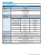
Страница 8: ...00V DC TP J2 4 Normal Line Sensing Under Voltage Dropout 11 18 Pickup 6 13 2 accuracy Dropout 18 Pickup 13 2 accuracy Normal Line Sensing Under Frequency 5 12 1 accuracy 12 1 accuracy Emergency Line...

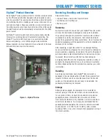
Страница 9: ...be taken to protect the equipment from impact at all times Do not remove the protective packaging until the equipment is at the installation site and ready to be installed After unpacking inspect the...

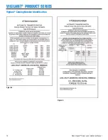
Страница 10: ...10 Ronk Vigilant Owner s and Installation Manual VIGILANT PRODUCT SERIES Vigilant Catalog Number Identification Figure 3 Figure 4...

Страница 11: ...sult in a system malfunction Mounting Requirements The enclosure has a NEMA National Electrical Manufacturer s Association type 3R rating and is suitable for indoor outdoor installations and provides...

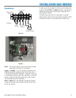
Страница 12: ...lues as shown in Table 1 and Table 2 WARNING Low voltage wire cannot be installed in the same conduit as power voltage wiring It could result in shock due to short circuit as well as cause electromagn...

Страница 13: ...e an isolated power supply to power the controller as the controller requires a reference to neutral for AC sensing which it obtains from the distribution system via Battery RSC1 and RSC2 need to be c...

Страница 14: ...time delay has expired the remote contacts will close sending a signal to the generator s automatic start controller When the control board senses that the generator has started and is within accepta...

Страница 15: ...a 12 OR 24 VDC system voltage In 12VDC system operation the controller requires that jumpers be installed in the 12 24VDC jumper location In 24VDC system operation the controller requires that no jump...

Страница 16: ...3 Weekly exercise with load no load ON Load test cycle OFF No load test cycle 4 Set the over under voltage setting OFF Dropout v 18 Pickup v 13 OFF Dropout v 17 Pickup v 12 OFF Dropout v 16 Pickup v...

Страница 17: ...to run under a no load condition until the engine cool time delay has expired TDES Time Delay Engine Start This delay prevents unnecessary engine starts When the control board determines a utility fai...

Страница 18: ...h will allow remote testing of the transfer switch The purpose of the test switch is to simulate a utility power failure The remote test switch may be installed by a licensed electrical contractor the...

Страница 19: ...ase note the flat side of the removable handle must face away from the power connection side of the switch mechanism as seen in Figure 12 for easy transferring Always remove the handle from the manual...

Страница 20: ...tion for possible safety hazards Inspect mounting location for any safety or fire hazards Inspect for dirt wiring damage and mechanical damage Inspect the transfer switch for loose hardware Check all...

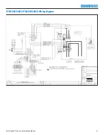
Страница 21: ...Wiring Diagram MATERIAL FINISH TITLE VIGILANT 100A 200AATS 2000 SERIES WIRING DIAGRAM 2 POLE 240V SCALE NTS REVISIONS 12 22 14 NEW ECO 031024 DEF E BL E CONSOLIDATED TERMINATIONS FOR NEW VENDOR 2 2 1...

Страница 22: ...ity of the transfer switch system The exact day and time may be specified for testing External LED indication is available for utility available generator NEMA 3 available transfer to utility transfer...

Страница 23: ...TE Unused ON and OFF times must have dashes not zeros The time of day is displayed in the 24 hour notation so 00 00 is midnight Program Review 1 Repeatedly press TIMER button to advance the display to...

Страница 24: ...ot be appropriate or applicable For example warranty service would not apply if equipment damage occurred because of misuse lack of routine maintenance shipping handling warehousing or improper instal...

Страница 25: ...Ronk Vigilant Owner s and Installation Manual 25 NOTES...

Страница 26: ...26 Ronk Vigilant Owner s and Installation Manual NOTES...

Страница 27: ...Ronk Vigilant Owner s and Installation Manual 27 NOTES...

Страница 28: ...RONK PO Box 160 106 East State Street Nokomis IL 62075 0160 Toll Free 800 221 7665 ronkelectrical com UG 001 02 1 2020...

Отзывы: