3.
Use the CURSOR buttons, if necessary, to select the row of
parameters containing Phaser Rate.
4.
Turn V1 [Phaser Rate] clockwise to make the swirling go faster—set
it to 2.0 Hz.
Adjust Your Effect-Related Levels
The effect-related levels for an insert effect are different than those for a
send-and-return effect: there are only two of them. As a result, they
perform somewhat different jobs:
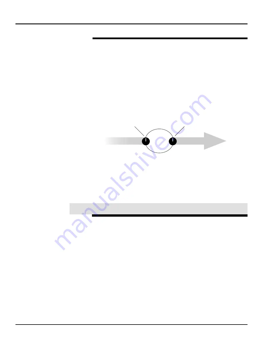
•
The effect input level sets the volume of the channel’s signal as it’s
diverted into the insert effect.
•
The effect output level sets the volume of the signal as it’s returned
back into the channel.
Here’s where the level controls are in our insert effect.
Let’s adjust these levels.
1.
Press PAGE DOWN twice.
2.
Make sure that the left channel of Effect 1 is selected, and turn V4
[SEND LEVEL] to set the effect’s input level to 100. This will make
the phasing even more pronounced, since you’re sending more
signal into the effect.
3.
Turn V5 [RETURN LEVEL] to set Effect 1’s output to 100. This will
restore the loudness of the signal to its original level.
When we discussed send-and-return effects, the effect algorithms we
used had mono inputs and stereo outputs—signals being sent into the
left and right inputs were combined as they went into the effect.
Some of the VM-7000’s effect algorithms have stereo inputs as well as
stereo outputs. With these algorithms, the left and right effect input
signals are processed separately by the effect. StDly-Chorus (Stereo
Delay Chorus), StPS Delay (Stereo Pitch Shifter Delay), Stereo Phaser
and Stereo Multi are all examples of stereo-in, stereo-out effects.
You can apply a stereo-in, stereo-out effect to a group of signals by
inserting the effect on two Flex Busses, combining elements of both
insert and send-and-return effects in a single setup: You insert the effect
on the pair of Flex Busses to which you’ve sent your input or multi in
signals, and you mix it in with the original dry signals as you would with
a send-and-return effect. (You also have the option of using the effected
Flex Bus signals alone, without mixing them in with the dry signals.)
We’ll send our signal from Input Channel 1 to the left side of an effect,
and the signal from Input Channel 2 to its right side.
©
2000 Roland Corporation U.S.
Getting Started with the VM-7000
2796US, v1.0
Page 40
Setting Up an Insert Effect (Continued)
®ÂØÒňÎ
Application Guide
Getting Started with the VM-7000
Input Channel 1 signal flow
Left side of
Effect 1
Input Channel 1 signal flow
1. Effect input level
2. Effect output level
XXVIII. Stereo-In, Stereo-Out Effects


